

Switched reluctance motor with double stators and double rotors
A switched reluctance motor, stator and rotor technology, applied in the direction of electrical components, electromechanical devices, magnetic circuit static parts, etc., can solve unsolved problems such as low vibration, low noise, etc., achieve amplitude reduction, electronic control reduction, The effect of increasing torque
- Summary
- Abstract
- Description
- Claims
- Application Information
AI Technical Summary
Problems solved by technology
Method used
Image

Examples
Embodiment 1
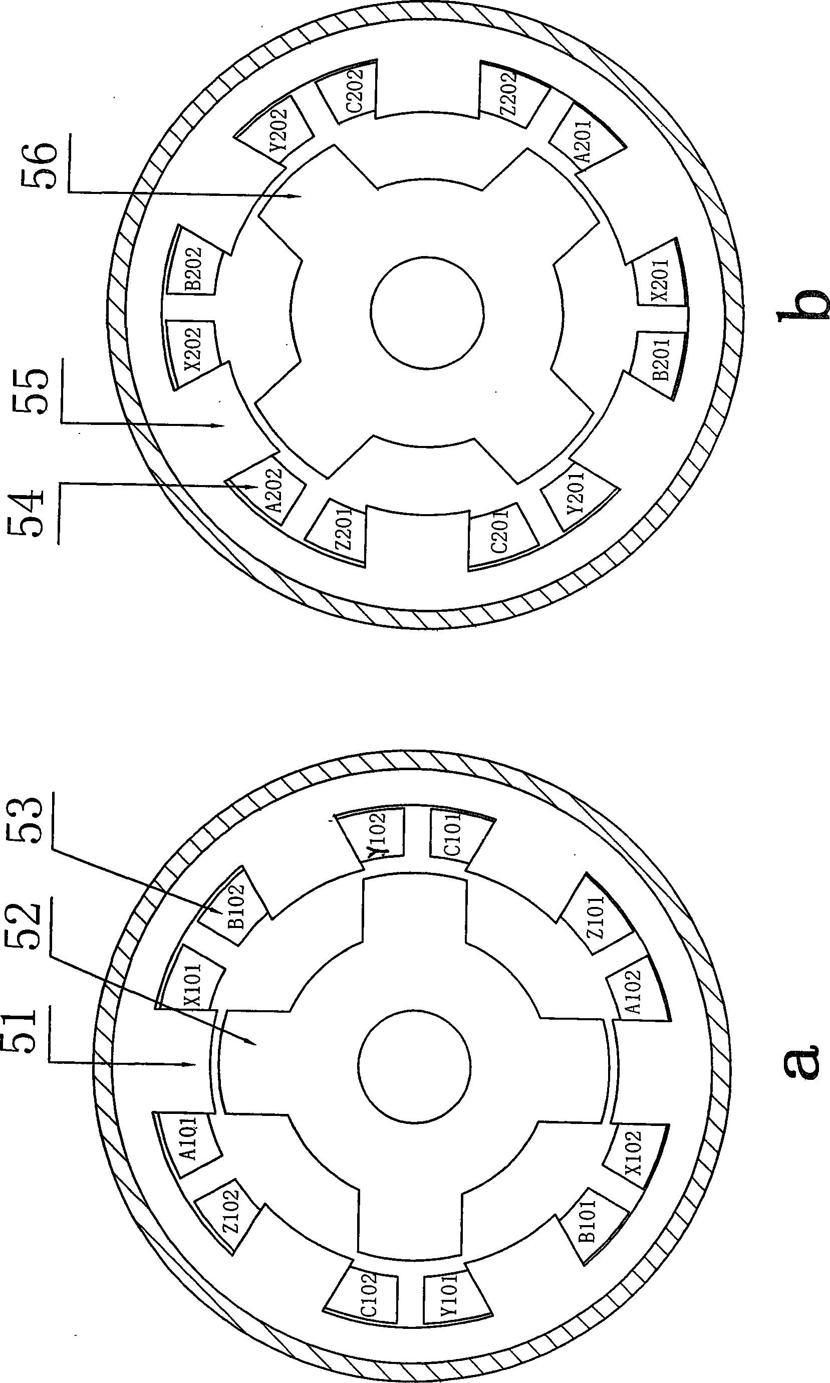
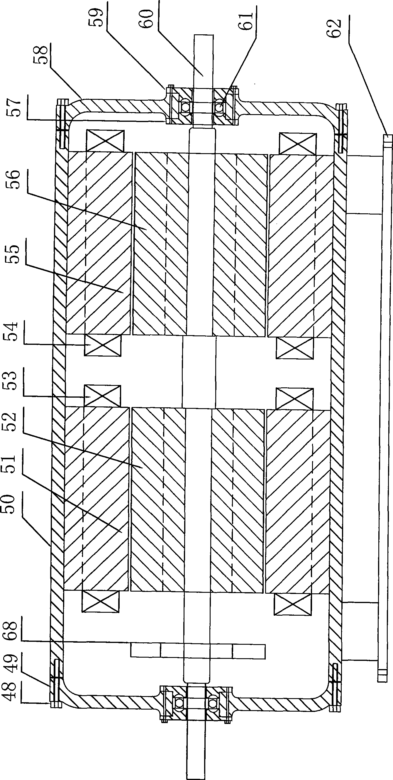
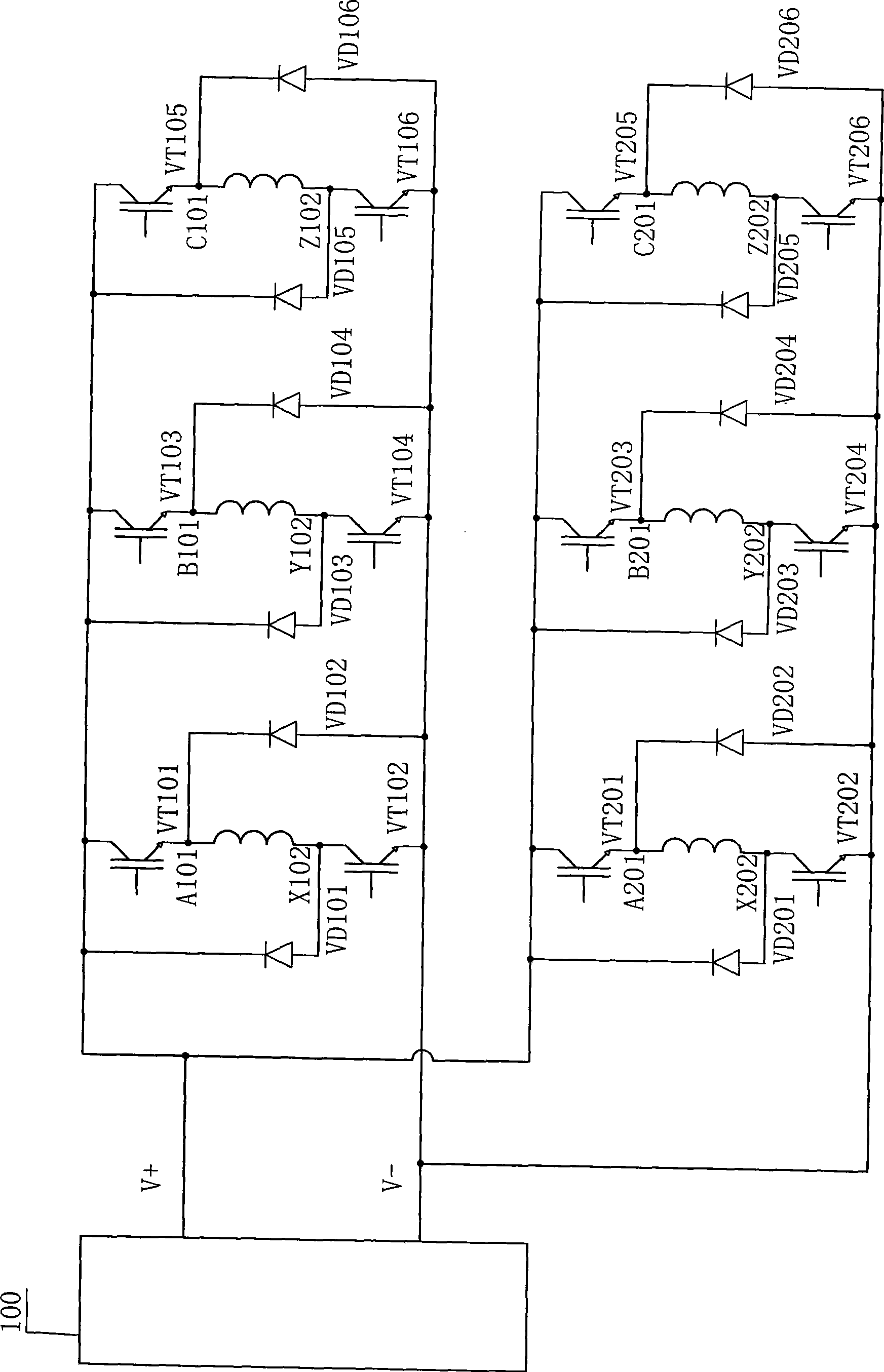
[0149] Embodiment 1 A double-stator-rotor switched reluctance motor (see figure 1 ), including the first section of stator 51, the second section of stator 55, the first section of rotor 52, and the second section of rotor 56, all of which are laminated by silicon steel sheets into a salient pole structure, and two sets of concentrated armature windings are respectively installed on the stator teeth 53 and 54, the armature windings on two teeth of the same phase of each set of windings are connected in series or in parallel to form a phase, the two stators and rotor cores have the same length, diameter, and frame size, and the two stators are staggered by 30 degrees Electrical angle; the two rotors are staggered by 45 degrees electrical angle.
[0150] The manufacture and installation of the first section stator 51 and rotor 52 are as follows: figure 1 As shown in a: the phase A stator magnetic poles are installed vertically at 90 degrees, the pair of magnetic poles of the fi...
Embodiment 2
[0188] Embodiment 2 A double-stator-rotor switched reluctance motor generator (see Figure 12 , Figure 15 ), including a stator, a rotor, a rotor excitation device and a driving device that are laminated with silicon steel sheets to form a salient pole structure. Armature windings, the armature windings on two teeth of the same phase of each set of windings are connected in series or in parallel to form a phase, the diameters of the two stator and rotor cores are the same, the frame size is the same, and the two rotors are equipped with excitation windings, and The two stators are staggered by an electrical angle of 30 degrees, and the two rotors are installed by a staggered electrical angle of 45 degrees.
[0189] The manufacture and installation of the first section stator 51, the rotor 52, the second section stator 55, and the rotor 56 are the same as in the first embodiment. The installation angle of the two-stage stator and rotor and the wiring of the winding can adopt...
Embodiment 3
[0202] Embodiment 3 A double-stator-rotor switched reluctance motor generator (see Figure 18 , Figure 20 ), including a stator, a rotor, a rotor excitation device and a driving device that are laminated with silicon steel sheets to form a salient pole structure. Armature windings, the armature windings on two teeth of the same phase of each set of windings are connected in series or in parallel to form a phase, the diameters of the two stator and rotor cores are the same, and the frame size is the same, and one of the two rotor sections is equipped with an excitation winding , and the two stators are staggered by an electrical angle of 30 degrees, and the two rotors are installed at an electrical angle of 45 degrees.
[0203] Stator 1 , rotor 52 and second section stator 55, rotor 56 are manufactured and installed with embodiment 1. The installation angle of the two-stage stator and rotor and the wiring of the winding can adopt the stator 2-pole connection method and the...
PUM
 Abstract
Description
Claims
Application Information