Device for influencing an exhaust gas flow

A technology of exhaust flow and driving equipment, which is applied in the direction of mechanical equipment, electric control of exhaust treatment devices, exhaust treatment, etc., can solve the problems of reliable continuous operation and danger, and achieve the effect of light size

Inactive Publication Date: 2009-07-15
ARVINMERITOR EMISSIONS TECH GMBH
View PDF0 Cites 2 Cited by
  • Summary
  • Abstract
  • Description
  • Claims
  • Application Information

AI Technical Summary

Problems solved by technology

In short, a negative spiral is thus started, so reliable continuous operation is at risk

Method used


Image

  • Device for influencing an exhaust gas flow
  • Device for influencing an exhaust gas flow
  • Device for influencing an exhaust gas flow

Examples


Embodiment Construction

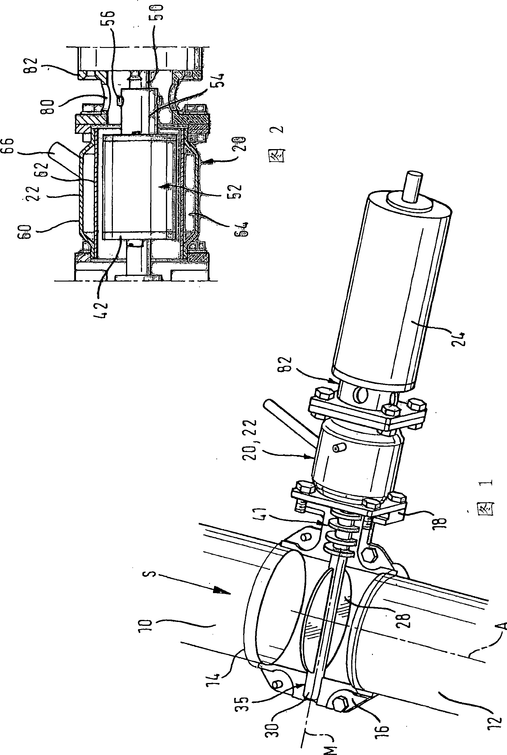
[0032] Figure 1 shows a device for disturbing the flow of exhaust gas, more precisely for controlling the acoustic emissions of the exhaust branch of a combustion engine. A tail gas supply pipe 10 supplies hot tail gas to the plant, while a duct 12 directs the hot tail gas from the plant towards the outlet. A linear section on one side of the device rests between the pipes 10, 12, which is concentric with said pipes and consists of two half-shells 14, 16 which are geometrically, formally And the size is the same.

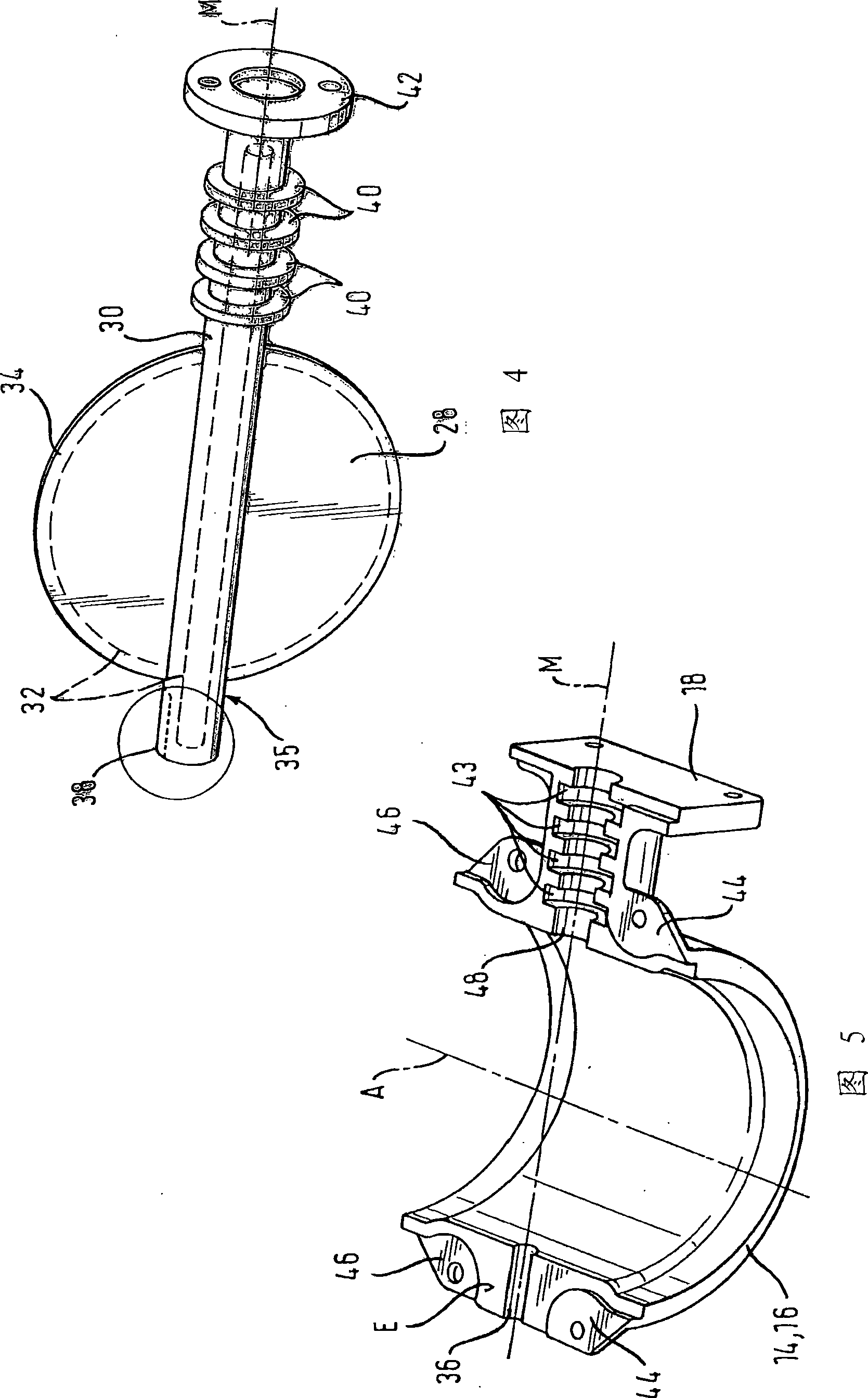
[0033] FIG. 5 shows one of the half shells 14 , 16 . The fastening flange 18 is formed integrally with the half-shells 14, 16, which are made of ceramic material or metal, preferably cast, and consists of two sections, each Associated with one of the half shells 14,16.

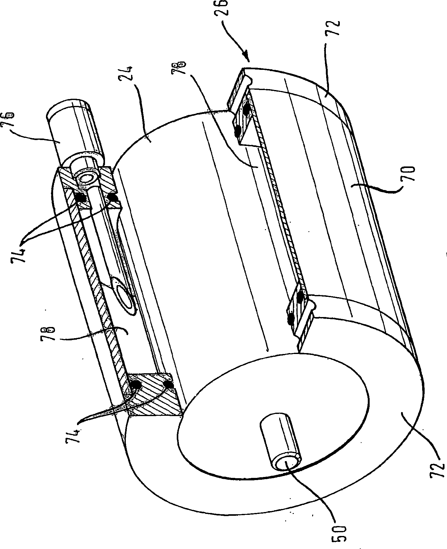
[0034] A unit consisting of a coupling 20 and an active cooling system 22 surrounding the coupling 20 (see FIG. 2 ) is flanged to the fastening flange 18 and has an electronic drive motor 24 with...


PUM


Abstract

The present invention relates to a exhaust gas (S) influencing device, especially used for controlling acoustic emission in vehicle exhaust system. The device including motor-driven closure element in exhaust pipe, said closure element generate pressure fluctuation in exhaust gas so as to proceed so-called 'acoustic design'. Thermal decoupling of force transmission device integrated into force transmission device which being accepted between drive motor (24) and closure element, the decoupling device absorb the thermal transmission between drive motor (24) and closure element.

Description

technical field [0001] The invention relates to a device for influencing the flow of exhaust gas, in particular for controlling acoustic emissions in an engine exhaust branch, with a closing member movably arranged in the exhaust gas flow and a drive device for the closing member, the drive The apparatus includes a drive motor and force transmission means coupling the drive motor to the closure member for driving, the closure member providing different flow resistances to the exhaust flow depending on its position in the exhaust flow. Background technique [0002] In order to meet legal requirements related to vehicle acoustic emissions, mufflers etc. are installed in the exhaust branch. For ever-increasing requirements, the design and testing effort of the entire exhaust system is enormous, as is the construction effort (costs, construction volume). In addition to legal requirements concerning sound emissions, so-called "sonic design" is also of great importance, especiall...

Claims


Application Information

Patent Timeline
Patent Type & Authority Applications(China)
IPC IPC(8): F01N1/16F01N1/18F01N7/14F02D9/04F01N13/08F01N13/14
CPCF02D9/04F01N1/165F01N2260/022F01N2560/08F01N2240/36F01N2560/14F01N2260/024F01N2390/02F01N1/168F01N1/18F01N9/00F01N13/14F01N13/16F01N2260/02F01N1/16
Inventor 赫尔穆特·翁豪斯尤维·诺尔特丹尼尔·科尔劳茨迈克尔·W·温策尔休伯特斯·西巴尔德
Owner ARVINMERITOR EMISSIONS TECH GMBH
Why Eureka
Try Eureka