
Biomass non-pressure gas making machine

A biomass and pressure technology, applied in the direction of manufacturing combustible gas, catalytic conversion of impurities, gas purification, petroleum industry, etc., can solve the problems of deactivation, waste of tar energy, tar difficult to completely burn, etc., to achieve stable operation, fast start-up, The effect of high gasification efficiency

Inactive Publication Date: 2012-05-09
熊天东
View PDF0 Cites 0 Cited by
  • Summary
  • Abstract
  • Description
  • Claims
  • Application Information

AI Technical Summary

Problems solved by technology

Low-quality solid biomass is food and agricultural and forestry crop waste (such as chaff, sawdust, straw), various combustible domestic and medical waste, and combustible waste derived from various industrial products. It is an inexhaustible alternative energy source and a precious renewable resource. However, the utilization technology of biomass energy in my country lags behind, and the utilization rate is less than 10%. Most of the rest are discarded or burned, which is a pity.
In the process of biomass gasification, the main problems after the generation of tar are: (1) tar accounts for 5%-10% of the combustible gas energy, and it is difficult to be burned and utilized together with the gas at low temperature, and the waste is serious; (2) Tar condenses into a liquid at low temperature, and is easy to combine with water and carbon particles to block gas pipelines, block valves, corrode metals, and cause normal combustion; (3) tar is difficult to burn completely and produces carbon black and other particles , causing serious damage to gas equipment; (4) tar and the smell it produces after burning have a slight damage to the human body
In the past, simple methods such as water washing or filtering only separated the tar from the gas, which not only wasted the energy of the tar itself but also produced a lot of pollution. Thermal cracking required a high temperature and sufficient residence time, and it was difficult to realize , the catalytic cracking method reduces the tar content in the gas, which is the most effective and advanced method at present, and is gradually adopted in large and medium-sized gasifiers
In catalytic cracking, the most critical issue is the selection of catalysts. A large number of experiments have proved that many materials have a catalytic effect on tar cracking, such as: Ni-based and heavy oil cracking catalysts, which have high activity and good effect. High cracking rate, but their cost is high, and carbon deposition is easy to cause its deactivation, so it is difficult to apply in general biomass gasification technology

Method used


Image

  • Biomass non-pressure gas making machine
  • Biomass non-pressure gas making machine
  • Biomass non-pressure gas making machine

Examples


Embodiment 1

[0028] Embodiment 1: There is only one set of gas production reaction device in the body

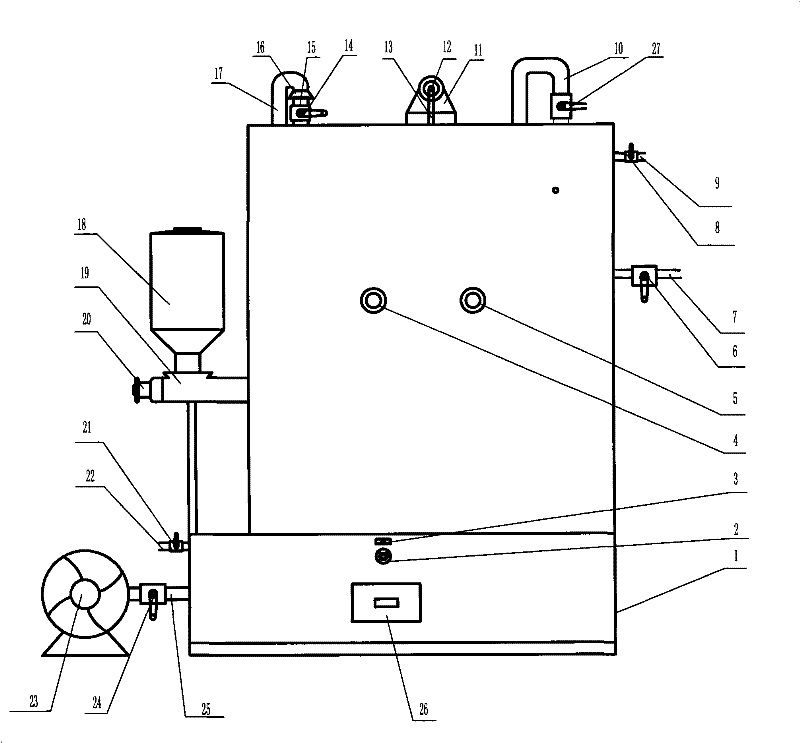
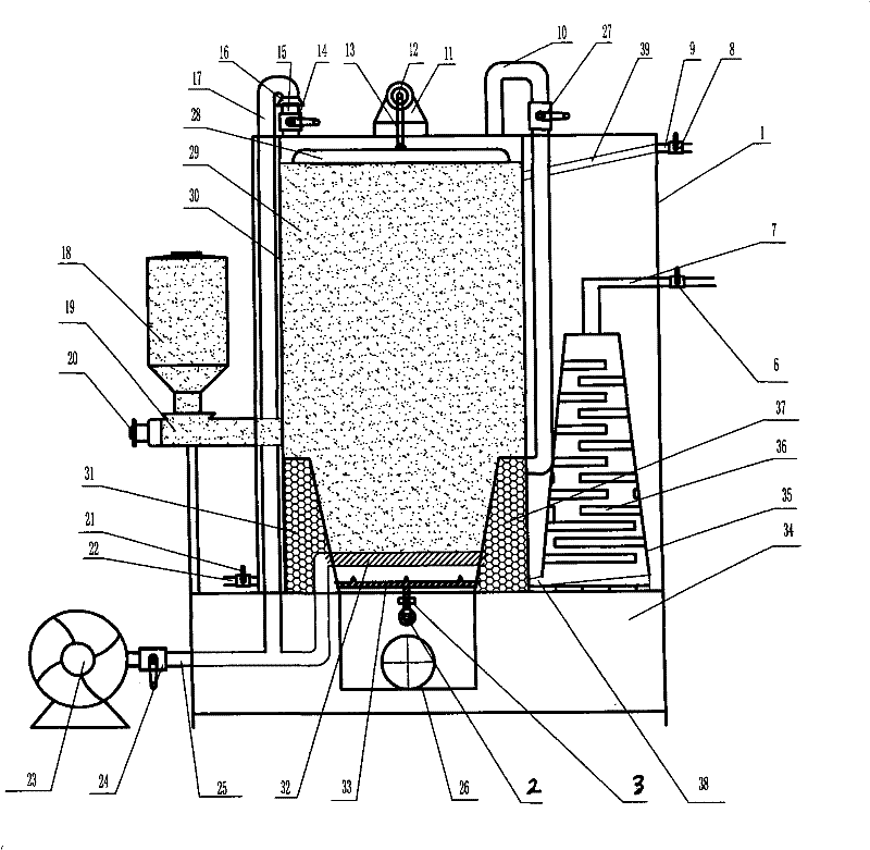
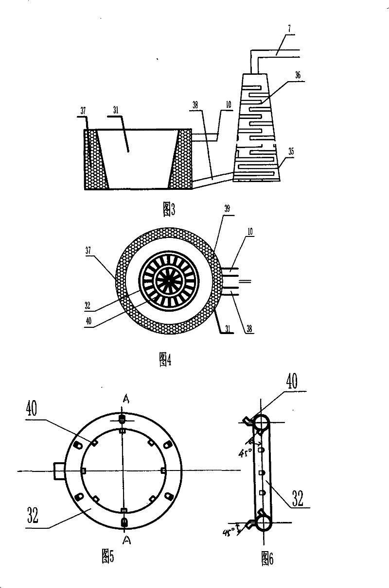
[0029] The present invention comprises a machine body 1, an air intake and oxygen aid device, a rotary ash removal device 2 installed in an ignition chamber 34 and a circulating hot water supply device, wherein the air intake and oxygen aid device consists of a blower 23 and a blower on the left side of the installation body 1 The air supply pipe 25 is formed, and the circulating hot water supply device is composed of the water inlet pipe 22 with the water inlet valve 21, the circulating water supply pipe 39 surrounding the outer wall of the gasification furnace body 30, and the hot water outlet pipe 9 with the water outlet valve 8. The outer upper part of the body 1 is equipped with a thermometer 4 and a pressure gauge 5 for displaying the temperature and pressure of the combustion chamber 29, an ash outlet 26 is arranged at the outer lower part of the body 1, and a gas production collis...

Embodiment 2

[0044] Embodiment 2: There are more than two sets of gas production reaction devices in the body

[0045] The structure of embodiment 2 is basically the same as embodiment 1, the difference is:

[0046] The body 1 is provided with a gas production collision reaction device 35 and more than two sets of gas production reaction devices connected in parallel or in series, and more than two sets of continuous feeding devices matching the gas production reaction device are arranged outside the body 1. Each set of waste water and tar The sub-pure gas output pipe 38 at the bottom end of the pyrolysis reaction device 31 is connected in series or in parallel with the bottom end of the gas production collision reaction device 35 .

[0047] Multiple sets of gas production reaction devices are connected together in parallel or in series, so that multiple sets of gas production reaction devices can work at the same time to achieve the purpose of large-scale gas production.


PUM

PropertyMeasurementUnit
particle diameteraaaaaaaaaa

Abstract

The invention discloses a biomass stress-free gas producing machine which comprises a machine, an air inlet oxygen-feeding device, a rotary dedusting device and a circulating hot water supply device; the biomass stress-free gas producing machine is characterized in that the machine is internally provided with a gas producing collision reaction device and more than one set of parallel-connected orserially-connected gas producing reaction device; each set of gas producing reaction device comprises a gasification furnace, a wastewater and tar high-temperature pyrolysis reaction device and a swaging actuating device; the wastewater and tar high-temperature pyrolysis reaction device is filled with dolomite; the secondary pure gas output tubes arranged at the bottom of each set of the wastewater and tar high-temperature pyrolysis reaction device are connected with the bottom of the collision reaction device after serially connected or parallel connected subsequently. The biomass stress-free gas producing machine is a novel gasification device to carry out second decomposition on the wastewater and tar by using the high-temperature chemical reaction of the wastewater and tar and the dolomite, which takes the dolomite as medium to carry out decomposition on the wastewater and tar by high temperature, so as to actually achieve the goals of zero emission, no secondary pollution, green environmental protection and large-scale gas production in the biomass gas producing technology.

Description

technical field [0001] The invention relates to combustion equipment, in particular to a biomass pressureless gas generator which uses low-quality solid biomass as a raw material for large-scale gas production. Background technique [0002] Biomass gasification technology refers to the use of oxygen or oxygen-containing substances in the air as a gasification agent to convert biomass into hydrogen-containing 2 , CO, CH 4 Process such as combustible gas. At present, biomass thermochemical conversion technology is the most practical one in gasification technology. It converts low-quality solid biomass into high-quality combustible gas. It can be widely used to drive internal combustion engines, heat generators for power generation and agricultural use. Irrigation equipment, or directly used for cooking, heating, crop drying and industrial product drying, etc. Low-quality solid biomass is food and agricultural and forestry crop waste (such as chaff, sawdust, straw), various ...

Claims


Application Information

Patent Timeline
Patent Type & Authority Patents(China)
IPC IPC(8): C10J3/20C10K1/34C10G11/02C10G11/18
CPCY02E20/18
Inventor 熊天东
Owner 熊天东
Learn More