Rotary-vane vertical wind energy engine

A technology of vertical rotary vane and wind energy machine, which is applied in the direction of wind power engine, wind power motor combination, wind power engine control, etc. It can solve the problems of difficult installation and maintenance, large floor space, low conversion efficiency, etc., and achieve stable power output , Small footprint, simple structure

Inactive Publication Date: 2009-07-22
陈小兵
View PDF0 Cites 23 Cited by
  • Summary
  • Abstract
  • Description
  • Claims
  • Application Information

AI Technical Summary

Problems solved by technology

The wind energy conversion equipment known to the general public is a fan whose axial direction is horizontal and the blades rotate vertically. Due to its low conversion efficiency, in order to obtain higher power, the diameter of the rotating blades is large, and the position of the axis is very high. Moreover, it occupies a l

Method used


Image

  • Rotary-vane vertical wind energy engine
  • Rotary-vane vertical wind energy engine
  • Rotary-vane vertical wind energy engine

Examples


Embodiment Construction

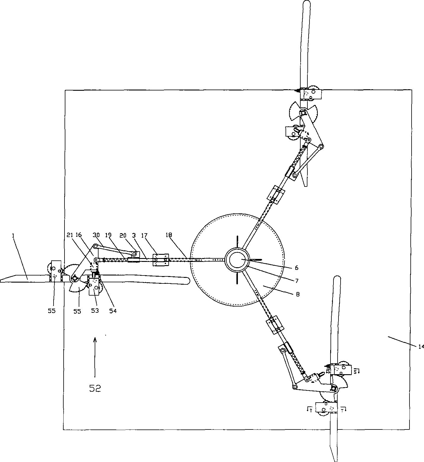
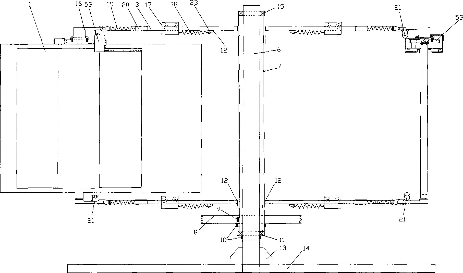
[0036] figure 1 , figure 2 is the first technical solution, figure 1 for top view, figure 2 It is a longitudinal section structure diagram, in which (1), one-side rotating blade, (3), one-side rotating blade support rod, (5), bearing, (7), transmission shaft, (12), welding point, ( 16), blade luffing seat, (21), buffer protector constitutes the rotor part, (17), centrifugal counterweight, (18), primary spring, (19), secondary spring, (20), connecting rod Push plate 1 type, (23), spring hook, (24), bolt, (30), connecting rod form speed regulation part; By (6), vertical shaft, (13), support rib plate, (14), base, Constituted support frame part; By (8), belt pulley, (9), key form power output part; Finally install (15), vertical shaft bearing, (10), retaining ring, (11), tapered roller bearing, form the first A technical solution is used for a rotary vane vertical wind energy machine without a fixed wind direction.

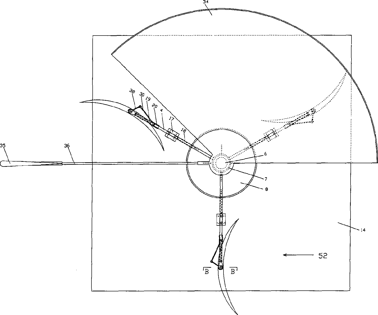
[0037] image 3 , Figure 4 is the second technical so...


PUM


Abstract

A rotary vane vertical wind driven generator outputs power by a vertical and horizontally rotating rotor, the rotor consists of a transmission shaft and a multiplate rotary vane annular array, the rotary vanes are divided into two kinds, one is unilateral rotating rotary vanes and the other is central shaft rotating rotary vanes. The wind energy generator has four technical proposals: the first is that the rotor consists of the unilateral rotating rotary vanes, wind area of the vanes is changed by a bumper guard, an expansion plate and a gear cluster, which causes the rotor to be unilaterally under stress, thus generating rotary motion; the second is that the rotor consists of the central shaft rotating rotary vanes, the rotor is unilaterally under stress by a wind shield, thus generating the rotary motion; the third is that the rotor consists of the central shaft rotary vanes, a shield plate is employed to protect the external cambered surface of a windward rotary vane from acting force, internal face of another shield plate inducts the wind to act on the internal cambered surface of the windward rotary vane so as to cause the rotor to be unilaterally under stress, thus generating the rotary motion; and the fourth is that the first and the second technical proposals are enlarged to perform multilayer and multiplate array mounting on the vanes.

Description

Technical field [0001] The invention belongs to a device for converting wind energy into kinetic energy, which can effectively improve the conversion efficiency and can be installed in places where the area is not spacious. Background technique [0002] Converting wind energy into kinetic energy is an environmentally friendly, economical and practical technology. The wind energy conversion equipment known to the general public is a fan whose axial direction is horizontal and the blades rotate vertically. Due to its low conversion efficiency, in order to obtain higher power, the diameter of the rotating blades is large, and the position of the axis is very high. Moreover, it occupies a large area, is difficult to install and maintain, and has high investment costs; the other is a vertical wind energy conversion device with a vertical axis and horizontally rotating blades; the prior art blades are fixed and both sides of the rotor are at the same time Under the force of the w...

Claims


Application Information

Patent Timeline
IPC IPC(8): F03D3/02F03D7/00F03D9/00
CPCY02E10/74
Inventor 陈小兵
Owner 陈小兵
Why Eureka
Try Eureka