Driver circuit and power source converter comprising the driver circuit

A technology for power converters and driving circuits, which is applied in the direction of output power conversion devices, instruments, electrical components, etc., can solve the problems of the overall price increase of power converters, general products without structure, and inconvenience.

Inactive Publication Date: 2012-01-11
LITE ON TECH CHANG ZHOU CO LTD +1
View PDF1 Cites 1 Cited by
  • Summary
  • Abstract
  • Description
  • Claims
  • Application Information

AI Technical Summary

Problems solved by technology

However, the cost of driving the chip is too high, and at the same time, the overall price of the power converter is relatively increased
[0014] It can be seen that the above-mentioned existing power converter obviously still has inconvenience and defects in structure and use, and needs to be further improved urgently.
In order to solve the above-mentioned problems, the relevant manufacturers have tried their best to find a solution, but no suitable design has been developed for a long time, and the general products do not have a suitable structure to solve the above-mentioned problems. This is obviously related. The problem that the industry is eager to solve

Method used


Image

  • Driver circuit and power source converter comprising the driver circuit
  • Driver circuit and power source converter comprising the driver circuit
  • Driver circuit and power source converter comprising the driver circuit

Examples


Embodiment Construction

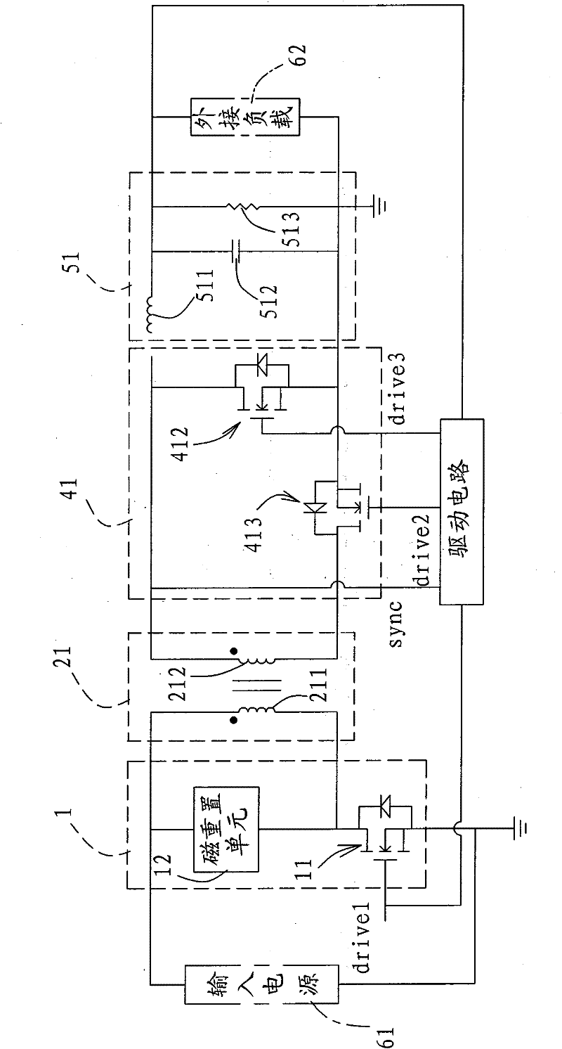
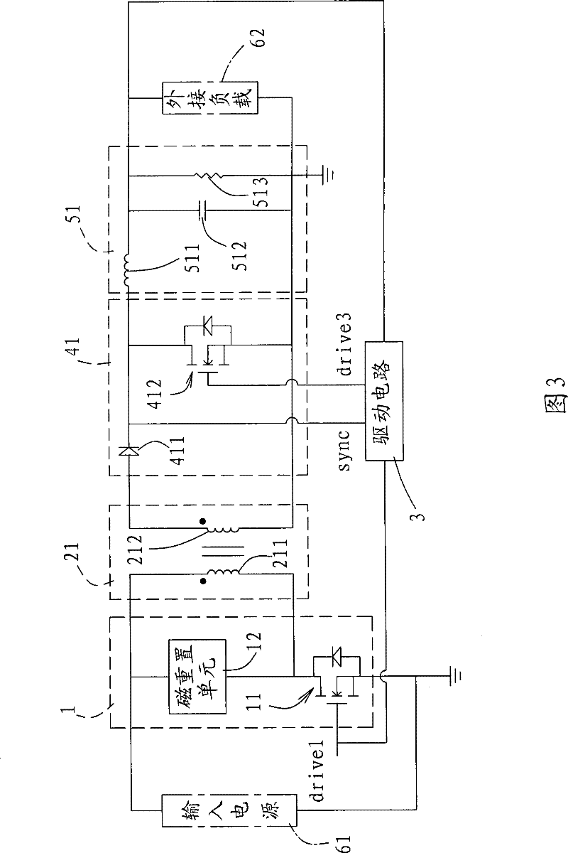
[0046] In order to further explain the technical means and effects of the present invention to achieve the intended purpose of the invention, the specific implementation of the driving circuit proposed according to the present invention and the power converter including the driving circuit will be described below in conjunction with the accompanying drawings and preferred embodiments. , structure, feature and effect thereof, detailed description is as follows.

[0047] The aforementioned and other technical contents, features and effects of the present invention will be clearly presented in the following detailed description of preferred embodiments with reference to the drawings. Through the description of the specific implementation mode, when the technical means and functions adopted by the present invention to achieve the predetermined purpose can be obtained a deeper and more specific understanding, but the accompanying drawings are only for reference and description, and ...


PUM


Abstract

The invention relates to a drive circuit and a power converter containing the drive circuit. The power converter comprises a main switch controlled by a driving signal, a main transformer receiving an input power supply in a switching way by the main switch, and a switching circuit which outputs a synchronizing signal and comprises a switch used for determining the receive status of an external connection load power supply; the drive circuit includes a dead pole time controller and an opposite phase generator; wherein, the dead pole time controller is provided with a second switch and a fourth switch, and the fourth switch is controlled by the synchronizing signal to control the conducting state of the second switch; the opposite phase generator is provided with a first switch and a fifthswitch which are controlled by the driving signal, and the fifth switch is controlled by the first and the second switches to output a switching signal that has the opposite phase to the driving signal, and the switching circuit is controlled; furthermore, dead pole time spacing is kept between the synchronizing signal and the switching signal. The invention can actively modify the switching signal, ensures the phenomenon of reverse current not to occur, leads the circuit to be synchronous and improves the drive capability by using the drive circuit.

Description

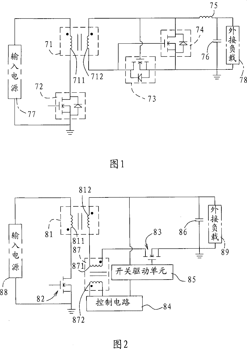
technical field [0001] The present invention relates to a drive circuit and a power converter including the drive circuit, in particular to an active correction drive circuit that can increase drive capability, prevent backflow, improve circuit synchronization, and reduce circuit cost, and includes The power converter for this drive circuit. Background technique [0002] see figure 1 Shown is a circuit diagram of an existing self-driven synchronous rectification power converter. The existing self-driven synchronous rectification power converter includes a main transformer 71, a driving switch 72, a rectifying switch 73, a circulating switch 74, an inductor 75 and a capacitor 76, and the main transformer 71 includes a first A coil 711 and a second coil 712 . [0003] A first terminal of the first coil 711 receives an input power 77 , a control terminal of the driving switch 72 receives a driving signal, and an external load 78 is connected in parallel with the capacitor. ...

Claims


Application Information

Patent Timeline
Patent Type & Authority Patents(China)
IPC IPC(8): H02M3/335H02M7/217
Inventor 陈志泰
Owner LITE ON TECH CHANG ZHOU CO LTD
Why Eureka
Try Eureka