Energy saving method for devices, energy saving device and system

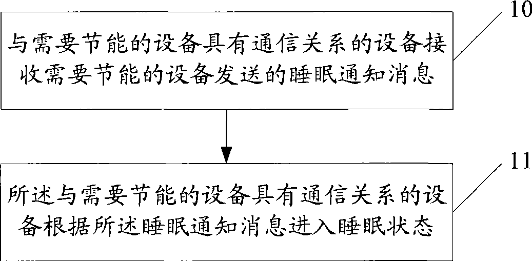
A technology of energy-saving equipment and equipment, applied in the field of communication, can solve the problems of energy consumption, failure, inability to achieve energy-saving effect, etc., and achieve the effect of effective energy-saving

Inactive Publication Date: 2009-07-22
HUAWEI TECH CO LTD
View PDF0 Cites 11 Cited by
  • Summary
  • Abstract
  • Description
  • Claims
  • Application Information

AI Technical Summary

Problems solved by technology

[0004] If the equipment at one end is in the energy-saving state or the link is in the energy-saving state, then the equipment that has a communication relationship with the equipment in the energy-saving state shows that the link is fau...

Method used


Image

  • Energy saving method for devices, energy saving device and system
  • Energy saving method for devices, energy saving device and system
  • Energy saving method for devices, energy saving device and system

Examples


example 1

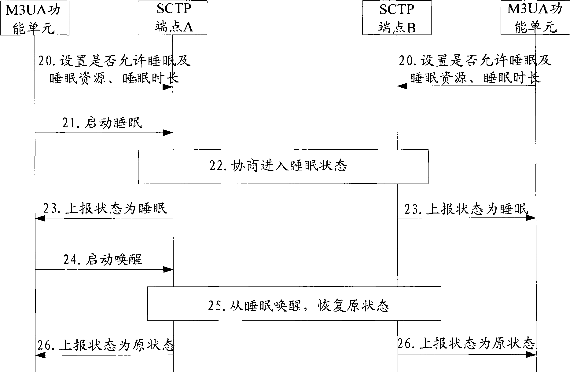
[0054] Example 1: The application scenario is to add the device sleep state in the SCTP communication connection, and the M3UA functional unit of the link layer controls the SCTP coupling completion sleep state notification of the transport layer. The coupling mentioned here refers to the communication connection relationship established between two SCTP endpoints. Such as figure 2 shown, including the following steps:

[0055] Step 20: The M3UA functional unit sets whether the SCTP endpoint is allowed to sleep, and sets the sleep resource and sleep duration, including the shortest (MinSleepTime) and / or longest sleep duration (MaxSleepTime);

[0056] Such as figure 2 As shown in , the SCTP endpoints in this example are SCTP endpoint A and SCTP endpoint B respectively, and the setting process of SCTP endpoint A and SCTP endpoint B is controlled by the M3UA functional unit on the side where the two endpoints are located.

[0057] Step 21: The M3UA functional unit on the sid...

example 2

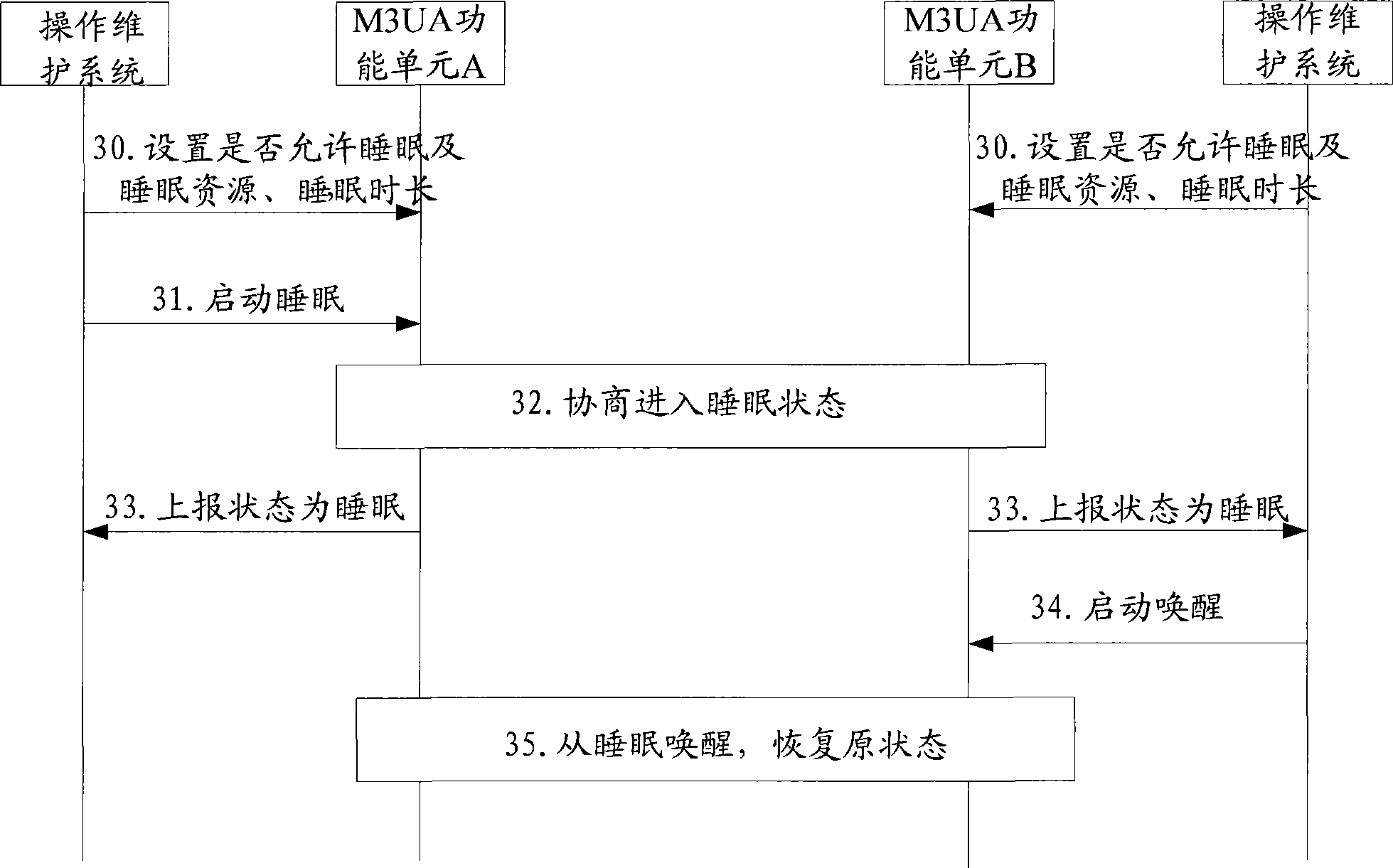
[0071] Example 2: The application scenario is to add a device sleep state in the SCTP communication connection, and the operation and maintenance system controls the M3UA functional unit of the link layer to complete the sleep state negotiation. Such as image 3 shown, including the following steps:

[0072] Step 30: the operation and maintenance system sets whether the M3UA functional unit of the link layer is allowed to sleep, and sets the sleep resource;

[0073] Such as image 3 As shown in , the M3UA functional units in this example are M3UA functional unit A and M3UA functional unit B, and the sleep setting process for M3UA functional unit A and M3UA functional unit B is controlled by the operation and maintenance system on the side where the two functional units are located.

[0074] Step 31: The operation and maintenance system on the side where the M3UA functional unit A and the M3UA functional unit B are located sends a start-sleep command to the M3UA functional un...


PUM


Abstract

An embodiment of the invention relates to an energy saving method of device in mobile communication field, wherein the method comprises receiving the sleep informing information transmitted by the device requiring energy saving by the device which has a communication relationship with the device requiring energy saving. The communication relationship comprises the communication channel which is established on a random layer or a plurality of layers of applied protocol between the devices for completing a certain service. The sleep informing information carries sleep resource which comprises the communication channel requiring entering sleep state. The device which has a communication relationship with the device requiring energy saving enters the sleep state according to the sleep informing information. The embodiment of the invention also relates to an energy saving device and system. The embodiment of the invention realizes the notifying to the device with communication relationship with the device when the latter device requires energy saving, thereby preventing the problem of energy consuming caused by the insignificant recovering attempting when the device is in energy saving state and the device mistakenly determines malfunction. The more effectively energy saving effect is obtained.

Description

technical field [0001] The present invention relates to the field of communication technologies, in particular to a device energy-saving method, an energy-saving device and a system. Background technique [0002] Energy saving is to reduce energy consumption as much as possible. For electronic equipment and computer equipment, it mainly refers to saving power consumption. Generally, there are multiple links between communication devices, and the links are in a redundant backup or load sharing relationship. For the device at one end of the link, the link is deployed on several processing units (a processing unit here refers to a physical or hardware resource, such as a single board). In the case of low business volume, only a part of links are needed to maintain corresponding business tasks. At this time, some processing units in the device may be in a state of standby, hibernation or shutdown to realize energy saving. That is, the energy-saving solution for communication ...

Claims


Application Information

Patent Timeline
IPC IPC(8): H04W24/04H04W28/18H04W52/02H04W80/00
CPCY02B60/50Y02D30/70
Inventor 赖荣文蔡建华
Owner HUAWEI TECH CO LTD
Why Eureka
Try Eureka