Metal oil tank production method

A production method and oil tank technology, applied in the field of mechanical processing, can solve problems such as uneven weld seams and inability to completely eliminate deformation, and achieve the effect of eliminating accumulated stress and ensuring flatness

Inactive Publication Date: 2009-07-29
傅凤义
View PDF1 Cites 19 Cited by
  • Summary
  • Abstract
  • Description
  • Claims
  • Application Information

AI Technical Summary

Problems solved by technology

However, the arrangement and welding sequence of the tank bottom plate of this patent application make the weld seam uneven, and the deformation cannot be completely eliminated, which affects its implementation.

Method used


Image

  • Metal oil tank production method
  • Metal oil tank production method
  • Metal oil tank production method

Examples


Embodiment 1

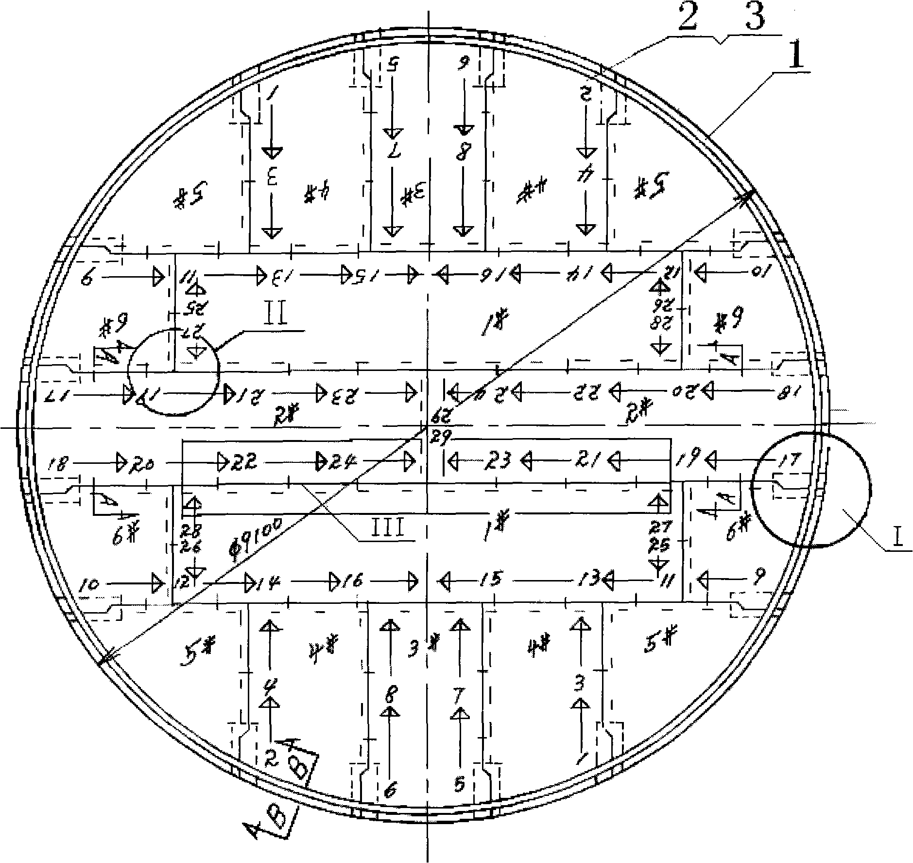
[0039] Such as figure 1 Shown, present embodiment tank volume V=500M 3 , height H=7980mm, tank bottom diameter Φ=9154mm, tank wall outer diameter Φ=9010mm. The material is A3F, the thickness of the tank wall steel plate is δ=5mm, and the thickness of the tank bottom steel plate is δ=7mm.

[0040] Calculation formula for bottom material of metal oil tank:

[0041] The first algorithm: when the outer diameter of the tank wall Φ is 9010mm,

[0042] Circumference = (9010+9010×6‰)×3.1416

[0043] =(9010+54.06)×3.1416

[0044] =9064.06×3.1416

[0045] =28475.65mm (circumference)

[0046] The second algorithm: when the outer diameter of the tank wall Φ is 9010mm,

[0047] Circumference=9010×3.1416×0.006+(9010×3.1416)

[0048] =28305.81×0.006+28305.81

[0049] =169.84+28305.81

[0050] =28475.65mm (circumference)

[0051] The actual cutting diameter of the bottom of the oil tank: when the circumference is 28475.65mm,

[0052] Φ=28475.65÷3.1416+(9100...

Embodiment 2

[0062] Present embodiment tank volume V=1000M 3 , height H=12690mm, tank bottom diameter Φ=11218mm, tank wall outer diameter Φ=11012mm. Material Q235-AF, Q235A, tank wall steel plate thickness δ=6mm, tank bottom steel plate thickness δ=6~7mm.

[0063] Calculation formula for bottom material of metal oil tank:

[0064] The first algorithm: when the outer diameter of the tank wall Φ is 11012mm,

[0065] Circumference = (11012+11012×8‰)×3.1416

[0066] =(11012+88.1)×3.1416

[0067] =11100.1×3.1416

[0068] =34872.1mm (circumference)

[0069] The second algorithm: when the outer diameter of the tank wall Φ is 11012mm,

[0070] Circumference=11012×3.1416×0.008+(11012×3.1416)

[0071] =34595.3×0.008+34595.3

[0072] =276.76+34595.3

[0073] =34872.1mm (circumference)

[0074] The actual cutting diameter of the bottom of the oil tank: when the circumference is 34872.1mm,

[0075] Φ=34872.1÷3.1416+(11130-11012)

[0076] =11100.1+118

[0077] =1...

Embodiment 3

[0085] Present embodiment tank volume V=2000M 3 , height H=11200mm, tank bottom diameter Φ=16076mm, tank wall outer diameter Φ=15830mm. Material Q235-AF, Q235A, tank wall steel plate thickness δ = 6-8mm, tank bottom steel plate thickness δ = 6-7mm.

[0086] Calculation formula for bottom material of metal oil tank:

[0087] The first algorithm: when the outer diameter of the tank wall Φ is 15830mm,

[0088] Circumference = (15830+15830×8‰)×3.1416

[0089] =(15830+126.64)×3.1416

[0090] =15956.64×3.1416

[0091] =50129.38mm (circumference)

[0092] The second algorithm: when the outer diameter of the tank wall Φ is 15830mm,

[0093] Circumference=15830×3.1416×0.008+(15830×3.1416)

[0094] =49731.53×0.008+49731.53

[0095] =397.85+49731.53

[0096] =50129.38mm (circumference)

[0097] The actual cutting diameter of the bottom of the oil tank: when the circumference is 50129.38mm,

[0098] Φ=50129.38÷3.1416+(15950-15830)

[0099] =15956.641+120

[0100...


PUM

PropertyMeasurementUnit
heightaaaaaaaaaa
thicknessaaaaaaaaaa
thicknessaaaaaaaaaa

Abstract

The invention relates to the field of mechanical processing, in particular to a welding production method for a metallic oil tank and a tank bottom. The method for producing the metallic oil tank comprises adopting a tank wall, an upper bottom plate of the tank bottom, a lower bottom plate of the tank bottom, an angle steel head, a tapered iron, and a liner plate. The method comprises the following steps: 1) performing the plate arrangement and numbering; 2) welding tank bottom plates and a tank wall plate, wherein firstly outside fillet welds between the tank bottom plates and the tank wall plate are welded, and then inside fillet welds between the tank bottom plates and the tank wall plate are welded; and 3) welding the tank bottom plates according to a numbering sequence. The method for producing the metallic oil tank is to draw a plate arrangement drawing according to the circular area of the tank bottom before the construction, weld longitudinal and transverse welds according to the sequence, calculate the shrinkage factor, and reserve adequate lapping allowance so as to avoid the hazard of sliding variable and stress concentration produced among the plates due to an action force of thermal expansion and cold shrinkage during the welding, and can effectively eliminate accumulated stress. The method for producing the metallic oil tank is applicable to the manufacturing and processing of metallic oil tanks with a volume of between 500 and 10,000 m.

Description

technical field [0001] The invention relates to the field of mechanical processing, in particular to a metal oil tank and a tank bottom welding manufacturing method. Background technique [0002] The traditional manufacturing method of metal oil storage tanks is to weld the middle plate first from the center to the outside, and then weld from the center to the outside with a segmented retreat method; According to the specific situation, the welding sequence of first welding the inner ring and then welding the outer ring can be adopted; the overlapping weld of the side plate should be welded from the inside to the outside with the step-back method; finally, the side plate and the Joining seams of medium boards. Due to the unreasonable arrangement of plates and lap joints in the traditional method of welding tank bottoms, the welding sequence causes concave-convex deformation after welding, and the stress of thermal expansion and contraction of large and medium-sized tank bot...

Claims


Application Information

Patent Timeline
Patent Type & Authority Applications(China)
IPC IPC(8): B23K31/02B23K101/12
Inventor 傅凤义
Owner 傅凤义
Why Eureka
Try Eureka