
Method for using porous ceramic on air humidification and air conditioning unit

A porous ceramic and air humidification technology, which is applied in air humidification systems, heating methods, air conditioning systems, etc., can solve the problems of high cost, limited humidification capacity, and unusability of normal temperature vaporization air humidification devices, and achieve considerable promotion and application value. The effect of low material cost and long service life

Active Publication Date: 2009-07-29
SHENZHEN LIANCHUANG TECHNOLOGY GROUP CO LTD
View PDF0 Cites 31 Cited by
  • Summary
  • Abstract
  • Description
  • Claims
  • Application Information

AI Technical Summary

Problems solved by technology

[0004] 1. Regardless of the above-mentioned humidification carrier, its surface area in contact with the flowing air is very limited, so the humidification amount is also very limited;
[0005] 2. The humidification carrier made of organic materials is not resistant to high temperature, and the humidification capacity cannot be increased by increasing the air temperature, especially for air conditioning devices that are adapted to air heating components;
[0006] 3. The humidifying carrier made of organic materials is prone to mildew and rot and breeds germs after being soaked in water for a long time, which is harmful to health;
[0008] Therefore, the humidification capacity of the room temperature vaporization air humidifier described in the prior art is the lowest among household humidifiers, and it is generally difficult to exceed 200 to 300 milliliters per hour, and the cost of the normal temperature vaporization air humidifier is also high, and the market share extremely low

Method used


Image

  • Method for using porous ceramic on air humidification and air conditioning unit
  • Method for using porous ceramic on air humidification and air conditioning unit
  • Method for using porous ceramic on air humidification and air conditioning unit

Examples


specific Embodiment

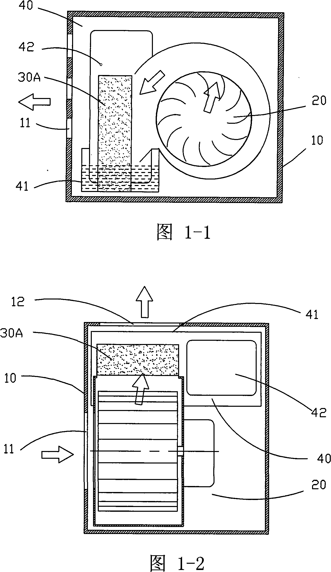
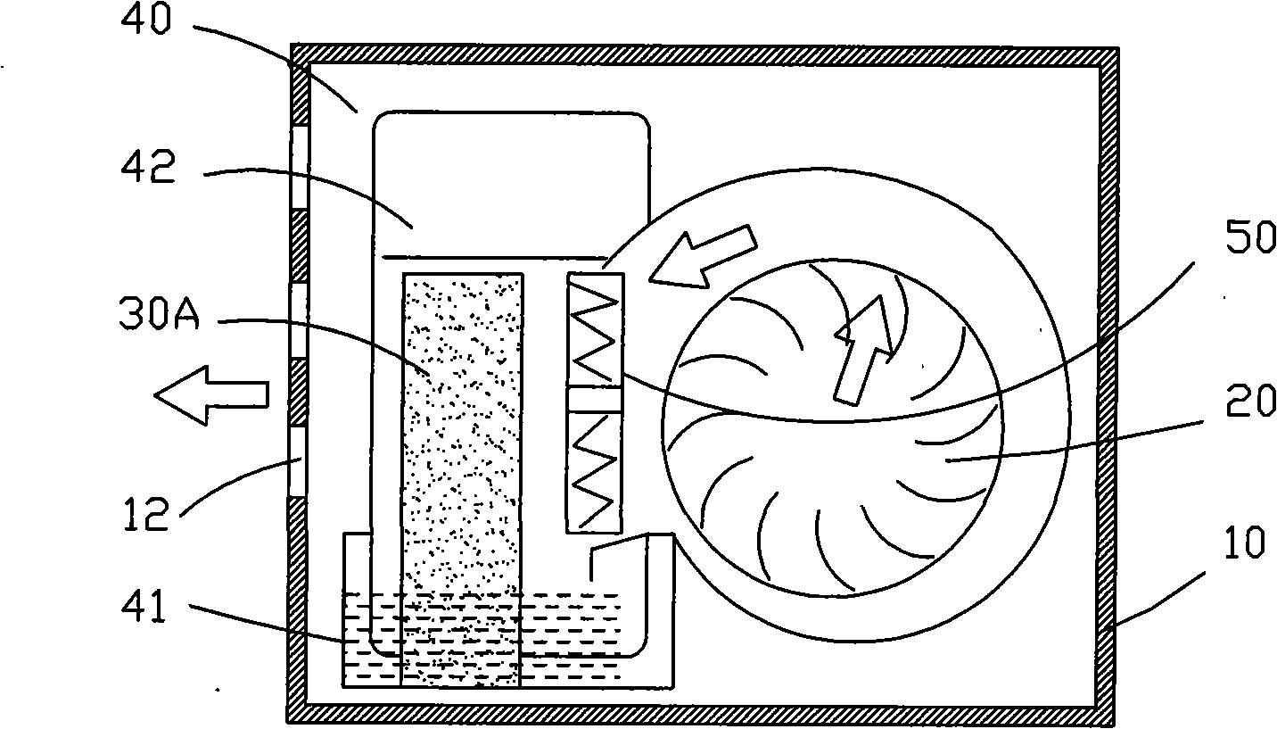
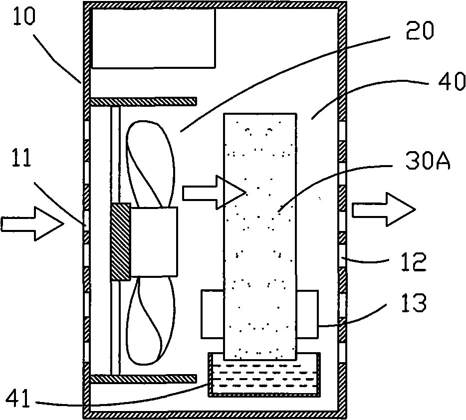
[0045] The first embodiment of the present invention, such as figure 1 As shown, the humidifying carrier is a cuboid-shaped porous ceramic body 30A. The fan 20 is a centrifugal fan. The water supply device 40 includes a water storage box 41 and a water tank 42; the perforated porous ceramic body 30A is vertically immersed in the water storage box 41; in order to automatically replenish the water in the water storage box 41, the water tank 42 includes smart valve 46; as Figure 9 As shown, the smart valve 46 is a valve device for automatically controlling the water level of the water storage box 41. In the first and second embodiments of the present invention, the smart valve 46 includes a valve cover 461, a valve stem 462, a valve plug 463 and Spring 464; the valve rod 462 passes through the valve cover 461 through the through hole of the valve cover 461, and one end of the valve rod 462 in the water tank 42 is connected to the valve plug 463, and the spring 464 is clamped o...


PUM

PropertyMeasurementUnit
porosityaaaaaaaaaa

Abstract

The invention relates to a method for applying porous ceramics to air humidification and an air conditioning device; in a vaporizing air humidification device based on normal temperature, flowing air blows over humidifying carrier used for absorbing moisture to vaporize the moisture on the surface thereof to water vapour into air, so as to improve air humidity; in the invention, the open-cell porous ceramics body is taken as the humidifying carrier; the open-cell porous ceramics body is high temperature resistant and has long service life, thereby lowering cost of the air humidification device. The invention also relates to an air conditioning device adopting the method; namely the open-cell porous ceramics body is taken as the humidifying carrier; as the porous ceramics body is high temperature resistant, manufacturing the air conditioning device with sole humidification function, sole heating function and both the humidification function and the heating function is feasible, and the method of vaporizing high-temperature air into water greatly improves humidification amount, saves electric power and has considerable popularization and application value.

Description

technical field [0001] The present invention relates to a method and a device for adjusting air humidity and temperature at home, in particular to a method of using a special material as a vaporization carrier of water and a domestic indoor air conditioning device using the method. Background technique [0002] Existing household air-conditioning installations include separate heating and humidification products, namely electric heaters and humidifiers. Although prior art electric heaters also have a humidification function, such as heat transfer medium oil circulation electric heaters (electric oil heaters) with humidification boxes, heaters with humidification components, etc., their humidification functions are all attached. Humidification cannot be done when heating; some electric heaters with ultrasonic humidifiers have strong humidification function, but due to the serious defects of ultrasonic humidifiers, they have been basically eliminated. Equally, although prior ...

Claims


Application Information

Patent Timeline
Patent Type & Authority Applications(China)
IPC IPC(8): F24F6/02A61L9/22F24F1/00
Inventor 赖伴来
Owner SHENZHEN LIANCHUANG TECHNOLOGY GROUP CO LTD
Learn More