Impedance matcher

A technology of impedance matching and impedance state, which is applied in the field of microelectronics and can solve problems such as inability to accurately monitor

Active Publication Date: 2009-07-29
BEIJING NAURA MICROELECTRONICS EQUIP CO LTD
View PDF0 Cites 7 Cited by
  • Summary
  • Abstract
  • Description
  • Claims
  • Application Information

AI Technical Summary

Problems solved by technology

However, the existing impedance matching device cannot accurately monitor the load at the output end, that is, the plasma impedance state, because there is no built-in component for monitoring the load state.

Method used


Image

  • Impedance matcher
  • Impedance matcher
  • Impedance matcher

Examples


Embodiment Construction

[0026] In order to make the purpose, technical solution and advantages of the present invention clearer, the present invention will be further described in detail below in conjunction with the accompanying drawings and specific embodiments.

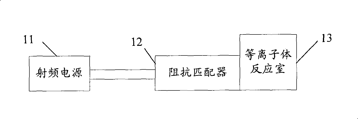
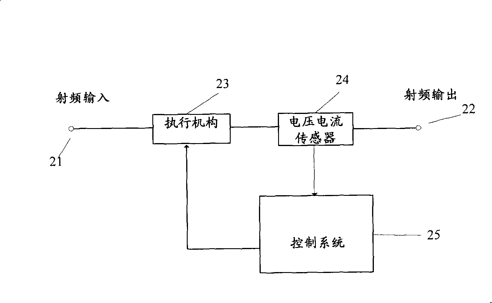
[0027] The impedance matching device of the present invention is located between the radio frequency power supply and the plasma reaction chamber, such as figure 2 As shown, it mainly includes an actuator 23, a voltage and current sensor 24 and a control system 25, wherein:

[0028] The radio frequency input terminal 21 is connected to the radio frequency output terminal 22 through the actuator 23 and the voltage and current sensor 24;

[0029] The voltage and current sensor 24 is arranged at the radio frequency output terminal 22, and is used for monitoring the impedance state in the plasma reaction chamber, and outputs a signal representing the impedance state of the plasma reaction chamber to the control system 25;

[0030] The actua...


PUM


Abstract

The invention provides an impedance matching device, which comprises: a voltage current sensor for monitoring impedance state in plasma reaction chamber and outputting plasma reaction chamber impedance state representation signal to control system; a control system for generating control signal according to before determined matching control method, driving actuating mechanism to adjust radio frequency power supply load impedance, and realizing the matching of radio frequency power supply output impedance and radio frequency power supply load impedance; acquiring the plasma reaction chamber impedance state representation signal from the voltage current sensor, and calculating plasma reaction chamber impedance value according to the plasma reaction chamber impedance state representation signal; and a actuating mechanism for receiving control signal of control system, and adjusting the radio frequency power supply load impedance according to the control signal. By adopting the above technical scheme, the invention realizes accurate monitoring to radio frequency power supply load impedance state.

Description

technical field [0001] The invention relates to microelectronic technology, in particular to an impedance matching device capable of accurately monitoring the load state. Background technique [0002] In a typical radio frequency plasma generator for manufacturing semiconductor devices, a radio frequency power supply with a constant output impedance (usually 50Ω) generates radio frequency waves with a fixed frequency (usually 13.56MHz) to provide radio frequency power to the plasma reaction chamber to The gas in the plasma reaction chamber is excited into plasma for etching or other processes. Generally speaking, the impedance of the nonlinear load of the plasma reaction chamber is not equal to the constant output impedance of the RF power supply, so there is a serious impedance mismatch between the RF power supply and the plasma reaction chamber, resulting in a large impedance on the RF transmission line. The reflected power of the RF power supply cannot be completely deli...

Claims


Application Information

Patent Timeline
Patent Type & Authority Applications(China)
IPC IPC(8): H05H1/46H01L21/00
Inventor 陈鹏
Owner BEIJING NAURA MICROELECTRONICS EQUIP CO LTD
Why Eureka
Try Eureka