
Cvd film forming method and cvd film forming apparatus

A film-forming method and a film-forming device technology, which are applied in the direction of gaseous chemical plating, coating, electrical components, etc., and can solve the problems of poor step coverage of PVD method

Inactive Publication Date: 2009-07-29
TOKYO ELECTRON LTD
View PDF1 Cites 2 Cited by
  • Summary
  • Abstract
  • Description
  • Claims
  • Application Information

AI Technical Summary

Problems solved by technology

However, in recent years, with the demand for finer wiring patterns, the step coverage of the PVD method is poor, and it is difficult to respond to the demand for miniaturization.

Method used


Image

  • Cvd film forming method and cvd film forming apparatus
  • Cvd film forming method and cvd film forming apparatus
  • Cvd film forming method and cvd film forming apparatus

Examples


Embodiment Construction

[0029] Embodiments of the present invention will be specifically described below with reference to the drawings.

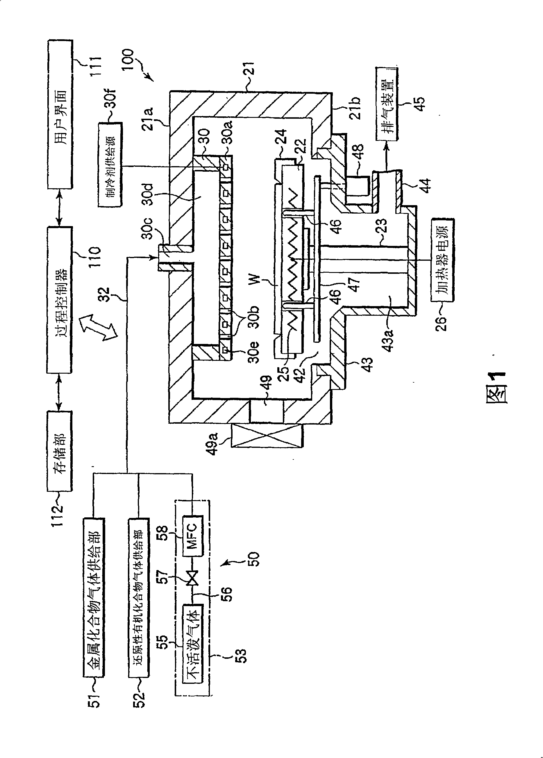
[0030] FIG. 1 is a cross-sectional view schematically showing a film forming apparatus for carrying out a CVD film forming method according to a first embodiment of the present invention.

[0031] The film forming apparatus 100 has a substantially cylindrical chamber 21 that is airtight. A circular opening 42 is formed at the center of the bottom wall 21b of the chamber 21, and an exhaust chamber 43 communicating with the opening 42 and protruding downward is provided on the bottom wall 21b. A susceptor 22 for horizontally supporting a wafer W as a semiconductor substrate is provided in the chamber 21 . The base 22 is supported by a cylindrical support member 23 protruding upward from the center of the bottom of the exhaust chamber 43 . A guide ring 24 for guiding the wafer W is provided on the outer edge of the susceptor 22 . A resistance heating type heater 2...


PUM


Abstract

The invention relates to a CVD film deposition process and apparatus. A wafer (W) is arranged on a susceptor (22) in a chamber (21), and a metal film is formed on the surface of a wafer (W) by continuously supplying the chamber (21) with a metal compound gas from a metal compound gas supplying section (51) and a reducing organic compound gas from a reducing organic compound gas supplying section (52) of a gas supplying mechanism (50).

Description

technical field [0001] The present invention relates to a CVD film-forming method and a CVD film-forming apparatus for forming, for example, a metal layer used in a semiconductor device by CVD. Background technique [0002] When manufacturing semiconductor devices, there is a process of forming a metal film for forming a wiring pattern. At this time, as a film forming method of the metal film, a physical vapor deposition (PVD) method typified by sputtering is often used. However, in recent years, with the demand for finer wiring patterns, the step coverage of the PVD method is poor, and it is difficult to meet the demand for miniaturization. [0003] Therefore, a CVD method utilizing a redox reaction using a metal compound gas and a reducing agent has attracted attention. However, in order to obtain a film of good quality, it is necessary to sufficiently reduce the metal compound gas. Therefore, Patent Document 1 discloses that after forming a metal oxide film by an ALD (at...

Claims


Application Information

Patent Timeline
Patent Type & Authority Applications(China)
IPC IPC(8): C23C16/18H01L21/02H01L21/28H01L21/285
CPCH01L21/76843H01L21/76873C23C16/045C23C16/18H01L21/28556H01L21/76861
Inventor 三好秀典
Owner TOKYO ELECTRON LTD
Learn More