High-speed precision punching machine

A precision punching, high-speed technology, applied in the direction of stamping machines, presses, manufacturing tools, etc., can solve the problems of easy deformation caused by eccentric force of guide column assembly tolerance, low stamping precision, difficult adjustment of ball head clearance, etc., to overcome stamping precision Low, stable operation, and compact structure of the punching machine

Inactive Publication Date: 2009-08-05
宁波米斯克精密机械工程技术有限公司
View PDF1 Cites 25 Cited by
  • Summary
  • Abstract
  • Description
  • Claims
  • Application Information

AI Technical Summary

Problems solved by technology

[0002] Patent application number 200810025932.6 "A high-speed precision CNC punching machine", which uses a ball-joint linkage mechanism at the junction of the connecting rod and the slider. Due to the high machining accuracy of the ball-joint linkage and the difficulty in adjusting the ball-joint clearance, it will cause high-speed The bottom dead center of the precision punching machine is unstable, the punching precision is low, and the work efficiency is not ideal
In addition, it uses a single-link mechanism in the dynamic balance, which is connected to the crankshaft through the bearing bush. Due to the large contact area of ​​the bearing bush and the large friction, the lubrication i

Method used


Image

  • High-speed precision punching machine
  • High-speed precision punching machine
  • High-speed precision punching machine

Examples


Embodiment Construction

[0012] Embodiments of the present invention will be further described below in conjunction with the accompanying drawings.

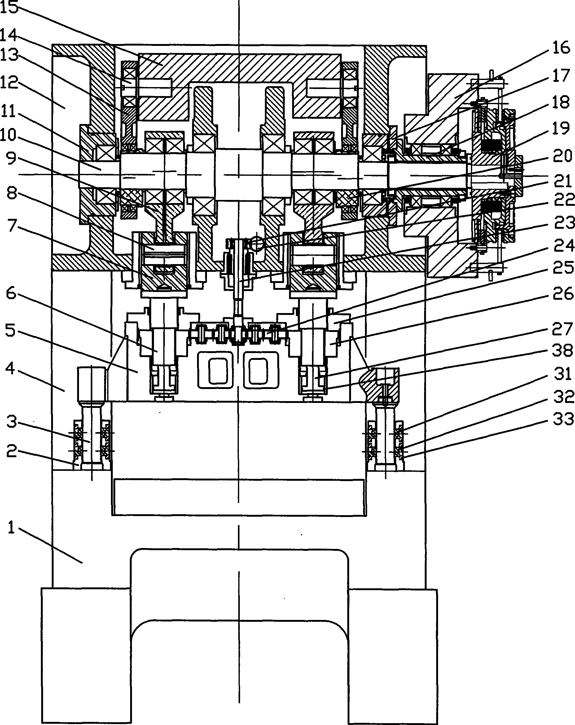
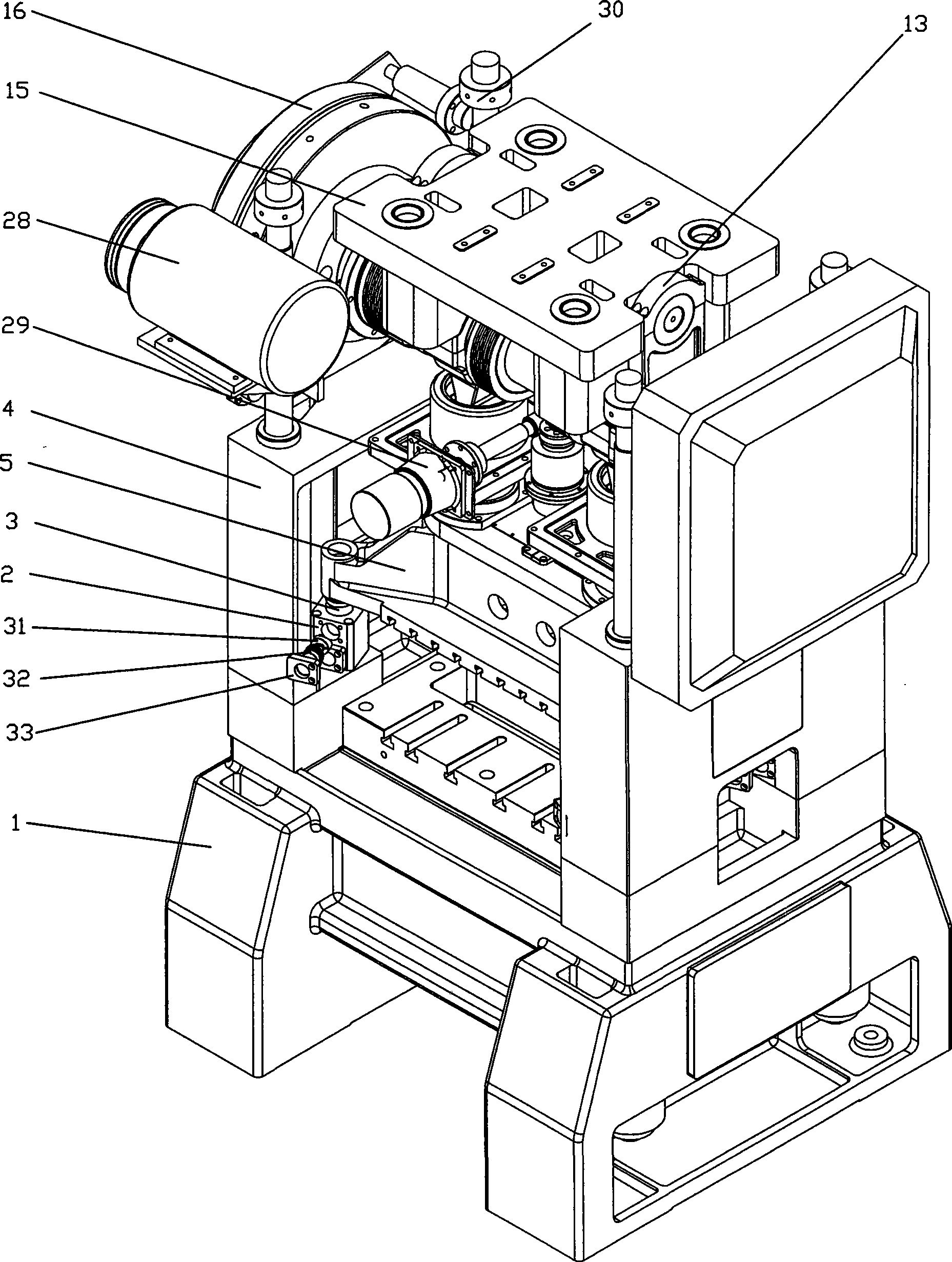
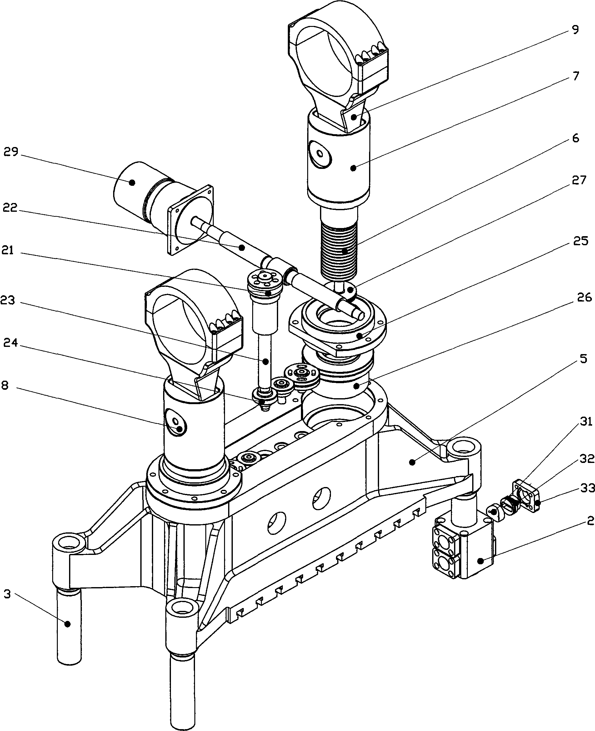
[0013] The dynamic balance part adopts a double-link mechanism. Since the crankshaft 10 is an eccentric shaft device, the eccentric force generated during the movement will cause left and right swings during the stamping process, so two sets of eccentric shafts are installed at both ends of the crankshaft. The collar 20 makes it opposite to the eccentric direction of the crankshaft 10, and is close to the end surface of the eccentric section of the crankshaft, and is connected to the two ends of the dynamic balance weight 15 through the double connecting rod 13 connected to it on both sides, the bearing, and the pin 14 , through the up and down movement of the dynamic balance weight 15 connected by two sets of eccentric collars 20 to offset the eccentric force generated by the crankshaft movement, thereby ensuring that the punching machine can work in bal...


PUM


Abstract

The invention relates to a dieing machine, which comprises a pedestal and an abutment body. A crankshaft transmission part is provided with a fly wheel, a clutch brake assembly, a dynamic balance piece, and one end of a connecting rod; the other end of the connecting rod is fixed on a slide block, the slide block is connected with a block adjusting and guiding device; a dynamic balance piece is provided with eccentric lantern rings which are arranged at two ends of a crankshaft; and a double connecting rob, a bearing and a pin which are connected with the eccentric lantern rings are connected with the dynamic balance piece to form the eccentric lantern rings, so that eccentric force generated by the motion of the crankshaft is offset, and left and right swing and deformation are prevented simultaneously. When processing different products, the dieing machine needs to change moulds and adjust the height of the slide block; and after the height of the slide is adjusted, a locking oil cylinder locks the slide lock so as to ensure that the position of the arranged mould does not change and the machining accuracy does not change. The slide block adopts a guide ring guiding structure so as to break a four guide pillar structure which is used for multiple years in punching machine industry. The over-positioning of the prior four guide pillar is replaced by the freely-jointed positioning of a guide sleeve, so that the assembling error can be solved through free displacement.

Description

technical field [0001] The invention relates to a high-speed punching machine for mechanical processing equipment, in particular to a high-speed precision punching machine. Background technique [0002] Patent application number 200810025932.6 "A high-speed precision CNC punching machine", which uses a ball-joint linkage mechanism at the junction of the connecting rod and the slider. Due to the high machining accuracy of the ball-joint linkage and the difficulty in adjusting the ball-joint clearance, it will cause high-speed The bottom dead center of the precision punching machine is unstable, the punching precision is low, and the work efficiency is not ideal. In addition, it uses a single-link mechanism in the dynamic balance, which is connected to the crankshaft through the bearing bush. Due to the large contact area of ​​the bearing bush and the large friction, the lubrication is insufficient, so poor lubrication is prone to heat generation, locking, and serious wear. T...

Claims


Application Information

Patent Timeline
IPC IPC(8): B21D28/00B30B1/14B30B15/00B30B15/02
CPCB30B1/266
Inventor 严海民彭进利
Owner 宁波米斯克精密机械工程技术有限公司
Why Eureka
Try Eureka