Measuring means for oilfield oil pump indicating diagram without load transducer

A load sensor and measurement method technology, applied in the direction of measuring devices, machines/engines, instruments, etc., can solve the problems of test equipment damage, sensor deformation measurement, burning distribution boxes, etc., to reduce production test costs and facilitate on-site control , the effect of prolonging the use time limit

Inactive Publication Date: 2009-08-05
山东亚华电子股份有限公司
View PDF0 Cites 14 Cited by
  • Summary
  • Abstract
  • Description
  • Claims
  • Application Information

AI Technical Summary

Problems solved by technology

Using this method, the load sensor is generally installed on the polished rod of the pumping unit. This type of sensor is more accurate, but easy to damage, and some are installed on the beam. This type of sensor is more durable, but less accurate
Before testing in this way, the preparation time for shutting down the well is long, which directly affects the production of the oil well. After the detection, the data processing time is long, and the time for drawing the dynamometer diagram is long, which directly affects the timeliness of taking measures for the problematic oil well, and often occurs. Electric box, burning motor, etc., will directly affect the normal production of oil wells in severe cases
In order to solve this problem, people have developed a permanent-mounted dynamometer tester. The method is generally to place the dynamometer sensor between the two splints of the rope suspension of the pumping unit for a long time. Deformation causes measurement errors, so the general sensor needs to be replaced and calibrated after about 3 months of use, which results in high testing costs for permanent-mounted dynamometers and cannot be further effectively promoted
In response to the above-mentioned problems, although some methods and devices for installing load sensors have appeared at present, which can be tested without stopping the machine, but because they all need to be installed with load sensors, there are still inconveniences in loading and unloading, prone to accidents, and damage to test equipment and other shortcomings

Method used


Image

  • Measuring means for oilfield oil pump indicating diagram without load transducer

Examples


Embodiment Construction

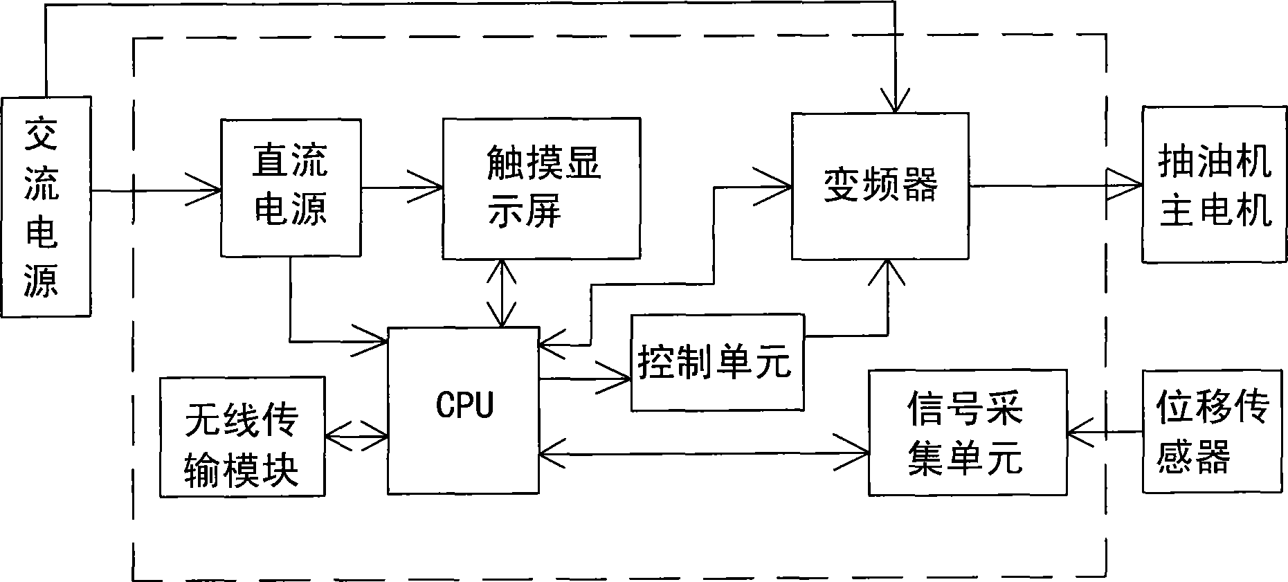
[0014] Embodiments of the present invention will be further described below in conjunction with accompanying drawings:

[0015] Such as figure 1 As shown, the AC power supply provides power to the DC power module. The DC power module provides DC power. The CPU controls the output of the frequency converter through the control unit, thereby controlling the operating states of the main motor of the pumping unit such as start, stop and speed. The data output end of the inverter is connected to the signal input end of the CPU, and the operation data of the inverter is sent to the CPU. The output data of the inverter includes current, voltage, torque, frequency, power, etc. The output end of the displacement sensor arranged on one side of the counterweight of the crank device of the pumping unit is connected to the signal input end of the CPU through the signal acquisition unit, and the displacement signal is sent to the CPU through the signal acquisition unit.

[0016] Collect...


PUM


Abstract

The invention relates to a method for measuring a indicating diagram of an oil filed oil extractor without a load sensor, which comprises the following steps: the indicating diagram of an oil filed oil extractor is used for measuring and calculating a self machine of an oil extractor, a CPU controls the operating state of a transducer through a control unit, the transducer controls a main motor of the oil extractor according to signals transmitted by the CPU, one side of a balancing weight block of a crank device of the oil extractor is provided with a displacement sensor which can transmit a displacement signal to the CPU through a signal collecting unit, the operating data of the collection transducer are transmitted to the CPU, the CPU carries out coordinate treatment for the displacement signal and the operating data of the collection transducer to obtain a main motor indicating diagram, the CPU carries out vectorial resultant treatment for the main motor indicating diagram and the oil extractor indicating diagram to obtain a feed rod indicating diagram of an oil extractor feed rod, and the feed rod indicating diagram comprises displacement data and load data. In the invention, load sensors, pressure sensors, and the like do not need to be arranged on the oil extractor feed rod or a walking beam, and the like, and the invention can accurately and reliably measure the indicating diagram of the oil extractor without stopping unloading, and the like.

Description

technical field [0001] The invention provides a method for measuring the dynamometer diagram of an oil field pumping unit without a load sensor, and belongs to the field of measuring the dynamometer diagram of an oil field pumping unit. Background technique [0002] Calculating and drawing the dynamometer diagram of the pumping unit in the oil field needs to measure the displacement value of the polished rod of the pumping unit and the load value of each displacement value. The existing pumping unit dynamometer measuring device in the oil field is an independent measurement system separated from the pumping unit. When measuring the dynamometer diagram of the pumping unit, it is necessary to stop for more than half an hour and install the load sensor and displacement sensor for measurement, that is, use the displacement sensor to measure the displacement value of the polished rod, use the load sensor to measure the load value, and then send it to the processing unit Process ...

Claims


Application Information

Patent Timeline
Patent Type & Authority Applications(China)
IPC IPC(8): F04B51/00G01B7/02E21B47/009
Inventor 耿玉泉
Owner 山东亚华电子股份有限公司
Why Eureka
Try Eureka