Ultra-discrimination differential confocal microscope with macro-micro view field observation

A differential confocal and super-resolution technology, applied in the field of super-resolution differential confocal microscopy, to avoid coherent imaging problems and simplify the operation process

Inactive Publication Date: 2009-08-05
BEIJING INSTITUTE OF TECHNOLOGYGY
View PDF1 Cites 37 Cited by
  • Summary
  • Abstract
  • Description
  • Claims
  • Application Information

AI Technical Summary

Problems solved by technology

However, the combination of optical imaging technology and CCD detection technology, the image analysis method is used to roughly align the sample position of the

Method used


Image

  • Ultra-discrimination differential confocal microscope with macro-micro view field observation
  • Ultra-discrimination differential confocal microscope with macro-micro view field observation
  • Ultra-discrimination differential confocal microscope with macro-micro view field observation

Examples


Embodiment Construction

[0023] The present invention will be further described below in conjunction with drawings and embodiments.

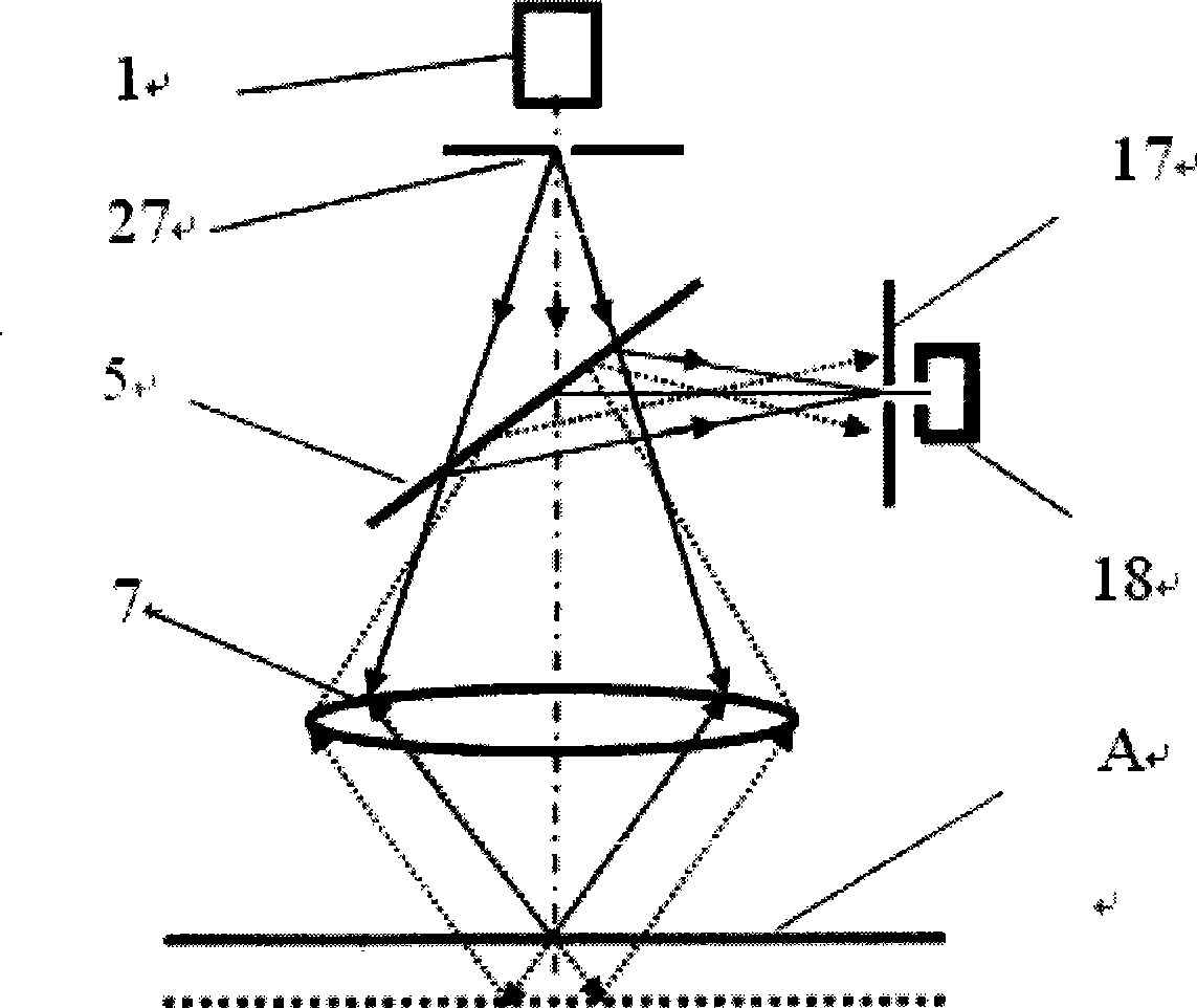
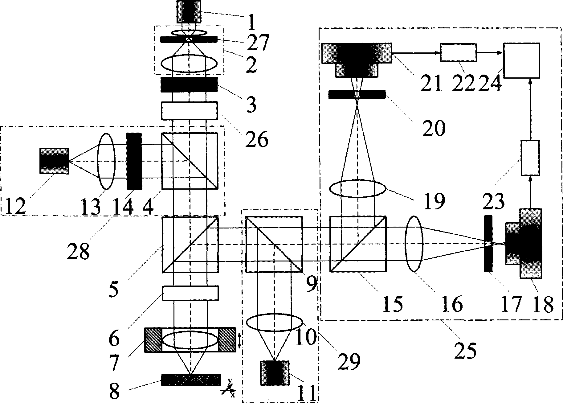
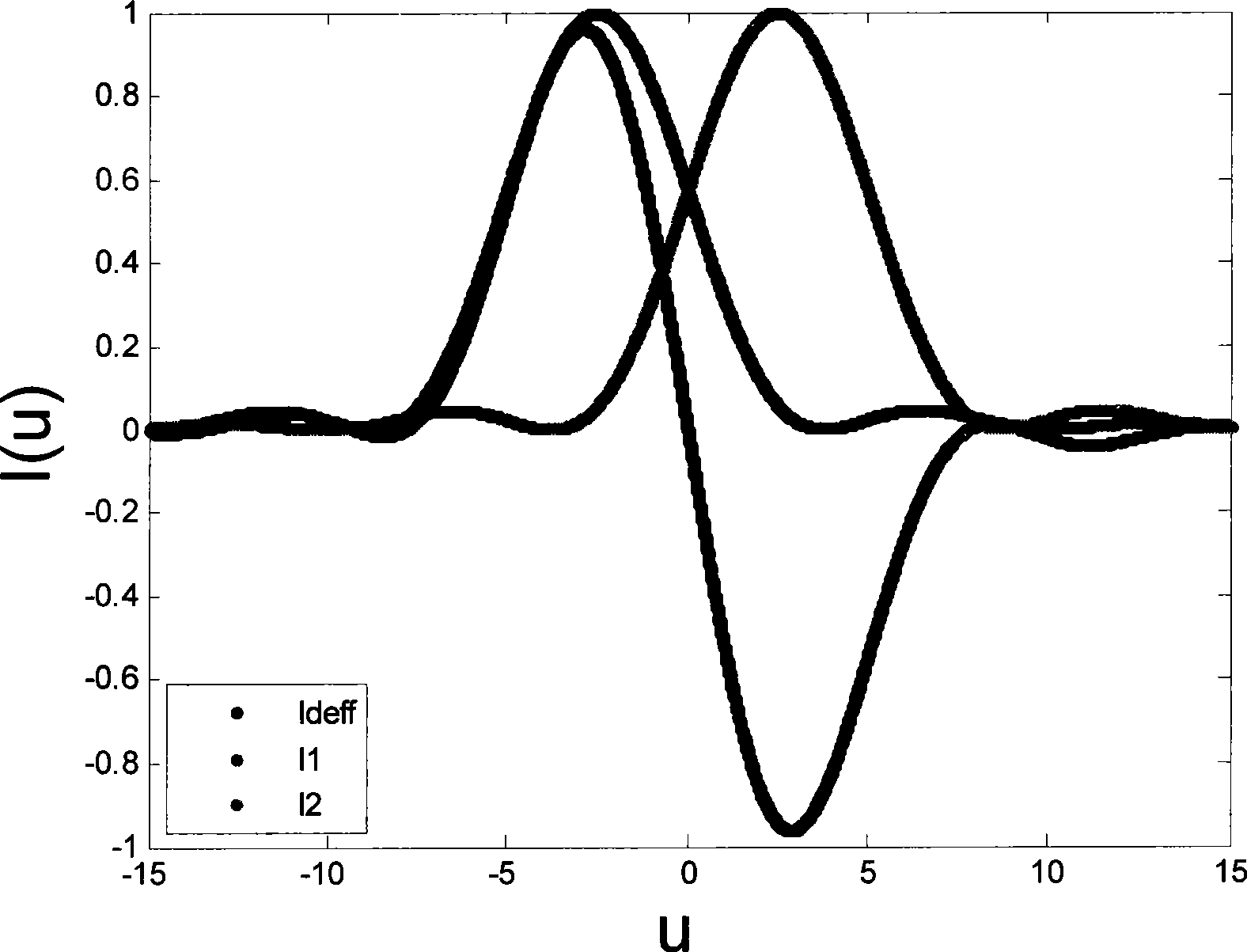
[0024] The technical principle of the present invention is: adopting the differential confocal microscopic imaging technology to arrange the receiving optical path of the confocal microscope into two detection optical paths before focus and after focus, and the two intensity response signals with different phases detected by the two detectors are differentially Subtraction achieves the purpose of improving the axial resolution and anti-interference ability; in addition, a low-coherence optical imaging system is introduced, and a CCD detector is used to receive imaging signals, so that the system has a macro-field observation function, which is convenient for the system to fix focus and be captured. The rough alignment of the test sample achieves the purpose of simplifying the operation process.

[0025] The structure diagram of the super-resolution differential confocal...


PUM


Abstract

The invention belongs to the technical field of optical microscopic imaging and optical precision measurement and relates to a super-resolution differential con-focal microscope with both macro field coverage observation and micro field coverage observation. The invention mainly comprises a laser (1), a beam expander (2), a spectroscope (4), a polarization spectroscope (5), a range extension tracking and measuring system (6), a measuring objective lens (7), two optical collectors (16) and (19), pinholes (17) and (20), detectors (18) and (21), an LED light emitting diode (12) which is arranged in a direction opposite to the reflection direction of the spectroscope and a CCD detector (11) which is arranged in a direction opposite to the reflection direction of a spectroscope (9). The LED light emitting diode and the CCD detector are used for realizing macro-field coverage observation of a con-focal microscope through imaging the surface type of the detected samples, and the axial resolution power of the con-focal microscope can be raised through deploying the optical path of the differential con-focal microscope.

Description

technical field [0001] The invention belongs to the technical field of optical microscopic imaging and optical precision measurement, and relates to a super-resolution differential confocal microscope with both macro-micro viewing field observation, which can be used for three-dimensional surface topography, three-dimensional microstructure, micro-steps, High-precision measurement of micro-grooves, micro-displacements, and line widths of integrated circuits. technical background [0002] In 1957, scholars such as M.Minsky in the United States first proposed the idea of ​​confocal microscopy in the study of optimizing the design of the microscope and trying to eliminate stray light, and was authorized by the US Patent Office in 1961, with the patent number US3013467. The imaging principle of the confocal microscope is to place the point light source, the point object to be measured, and the point detector in the corresponding conjugate position, which constitutes a tomographi...

Claims


Application Information

Patent Timeline
IPC IPC(8): G02B21/00
Inventor 赵维谦王允邱丽荣
Owner BEIJING INSTITUTE OF TECHNOLOGYGY
Why Eureka
Try Eureka