Controller for electric vehicle
A technology of electric vehicle control and electric power, applied in the direction of electric vehicles, electric vehicle charging technology, motor vehicles, etc., to achieve the effect of reducing energy consumption and reducing energy consumption
- Summary
- Abstract
- Description
- Claims
- Application Information
AI Technical Summary
Problems solved by technology
Method used
Image
Examples
Embodiment approach 2
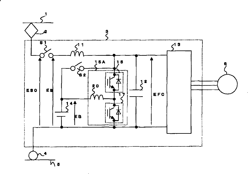
[0083] Figure 4 It shows a configuration example of a control device for an electric vehicle in Embodiment 2 of the present invention.
[0084] Figure 4 The structure shown with figure 1 Compared with the structure of the first embodiment shown, one end of the connection of the switch S2 is changed from the positive side of the power storage element 14 to the connection point of the switching elements 16 and 17 . When the switch S2 is turned on, the power storage element 14 is connected in parallel to the capacitor 12 without passing through the switching elements 16 and 17 .
[0085] Since other parts have the same structure as that of Embodiment 1, the same reference numerals are assigned and descriptions thereof are omitted.
[0086] According to the configuration of the second embodiment, the power storage element 14 and the inverter 13 can be connected via the reactor 20 . Connecting the power storage element 14 and the inverter 13 via the reactor 20 prevents the p...
Embodiment approach 3
[0092] Figure 5 It is a diagram showing a configuration example of a control device for an electric vehicle in Embodiment 3 of the present invention.
[0093] Figure 5 The structure shown with figure 1 Compared with the configuration of the first embodiment shown, the feature is that the switch S2 is deleted and the operation mode is added to the DCDC converter 15A. Since other parts have the same structure as that of Embodiment 1, the same reference numerals are assigned and descriptions thereof are omitted.
[0094] Such as Figure 5 As shown, Embodiment 3 is characterized in that switch S2 is not provided, and this function is replaced by switching element 16 of DCDC converter 15A.
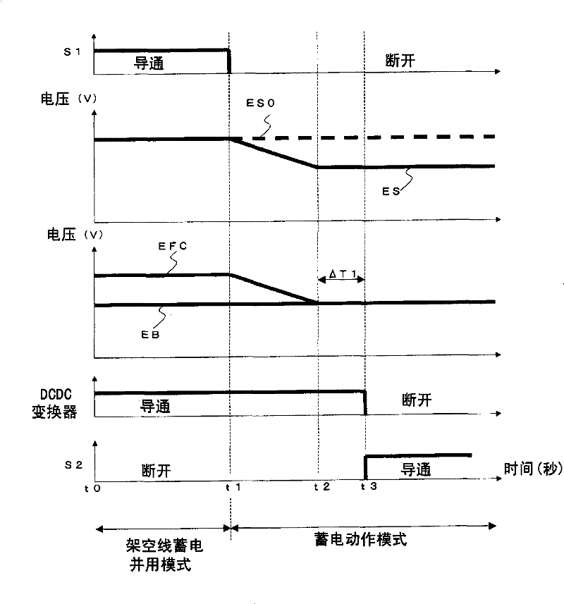
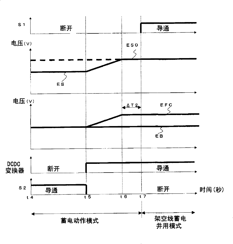
[0095] That is to adopt the following structure, that is, in Embodiment 1 ( figure 2 , image 3 ) at the time when the switch S2 is turned on, the switching element 16 is fixed to be on (the switching element 17 is fixed to be off). By fixing the switching element 16 to conduction, t...
Embodiment approach 4
[0100] Figure 6 It is a diagram showing a configuration example of a control device for an electric vehicle in Embodiment 4 of the present invention.
[0101] Figure 6 The structure of Embodiment 4 shown is the same as figure 1 Compared with the structure of the first embodiment shown, the characteristic feature is that the DCDC converter 15A is changed to a DCDC converter 15B. Since other parts have the same structure as that of Embodiment 1, the same reference numerals are assigned and descriptions thereof are omitted.
[0102] Figure 6 Among them, the DCDC converter 15B is characterized in that it is composed of a so-called bidirectional buck-boost DCDC converter circuit including switching elements 16 to 19 that perform PWM operations; reactors 20 and 22; and a capacitor 21, and can perform power control in any direction. , not depending on the relationship between the voltage EB of the power storage element 14 and the inverter input voltage EFC.
[0103] Therefor...
PUM
 Abstract
Description
Claims
Application Information
 - R&D
- Intellectual Property
- Life Sciences
- Materials
- Tech Scout
- Unparalleled Data Quality
- Higher Quality Content
- 60% Fewer Hallucinations
Browse by: Latest US Patents, China's latest patents, Technical Efficacy Thesaurus, Application Domain, Technology Topic, Popular Technical Reports.
© 2025 PatSnap. All rights reserved.Legal|Privacy policy|Modern Slavery Act Transparency Statement|Sitemap|About US| Contact US: help@patsnap.com


