
Apparatus and method for charge pump slew rate control

A slew rate and charge pump technology, which is applied to equipment and fields for charge pump slew rate control, and can solve problems such as unnecessary degradation of memory cells

Inactive Publication Date: 2009-08-05
ATMEL CORP
View PDF0 Cites 8 Cited by
  • Summary
  • Abstract
  • Description
  • Claims
  • Application Information

AI Technical Summary

Problems solved by technology

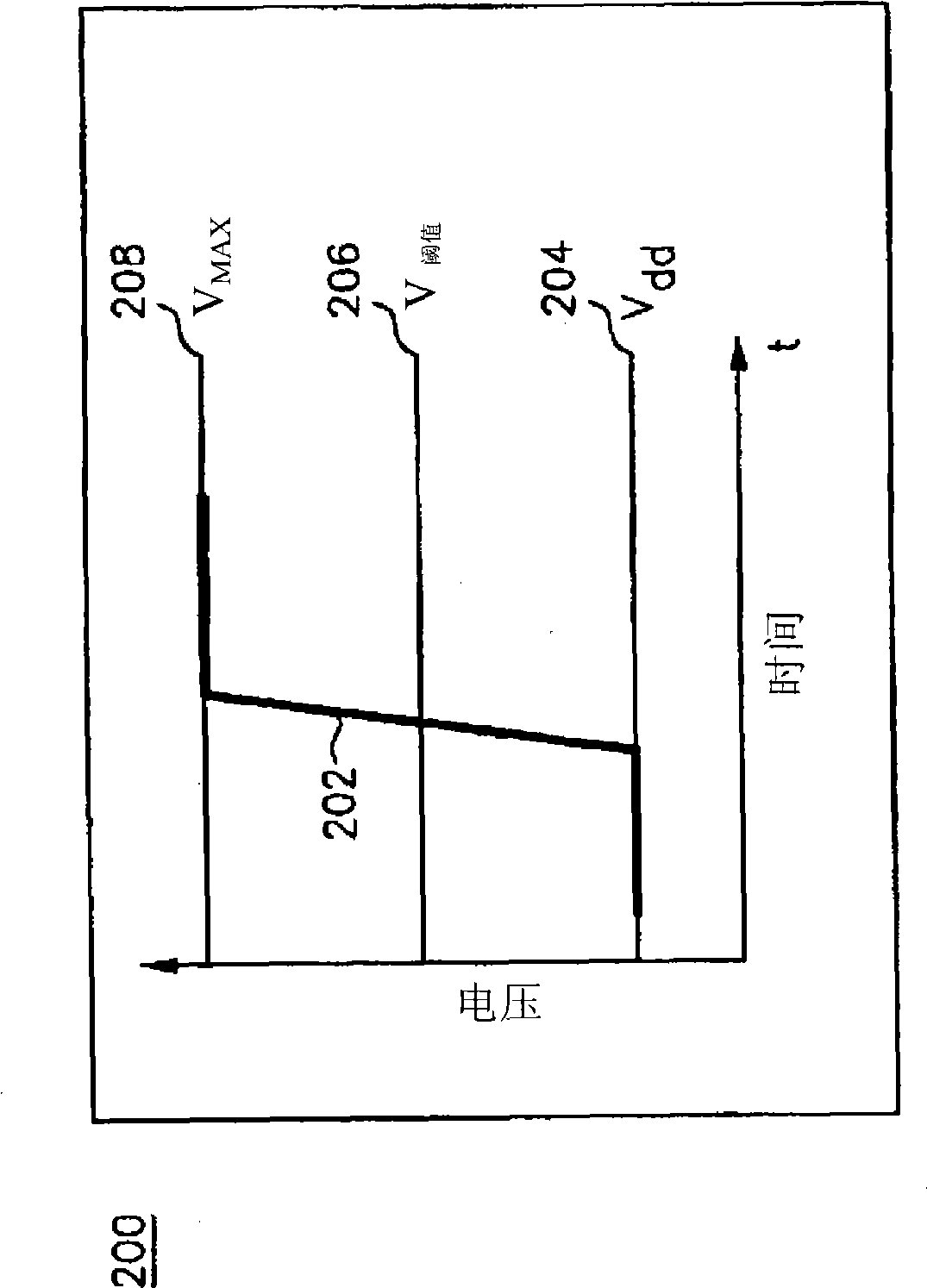
The prior art slew rate 202 can cause unnecessary degradation of memory cells

Method used


Image

  • Apparatus and method for charge pump slew rate control
  • Apparatus and method for charge pump slew rate control
  • Apparatus and method for charge pump slew rate control

Examples


Embodiment Construction

[0018] The invention is described below by the ref drawings, wherein like numerals refer to like elements throughout. For the purpose of describing the invention, the phrase high voltage level is used. It should be understood that the term "high" is a relative term and not necessarily a fixed voltage. Thus, the phrase high voltage may be any voltage and may vary based on, for example, processing technology and / or the material in which the memory cell is implemented. The term "level" may denote a fixed voltage or a range of voltages, as appropriate. Memory cell 100 is used purely as an example. The invention can be used in any memory device or memory cell. Examples of memory devices include parallel or serial electrically erasable programmable read only memory (EEPROM) and flash memory. Additionally, a node and a voltage at a node are used interchangeably in the following description.

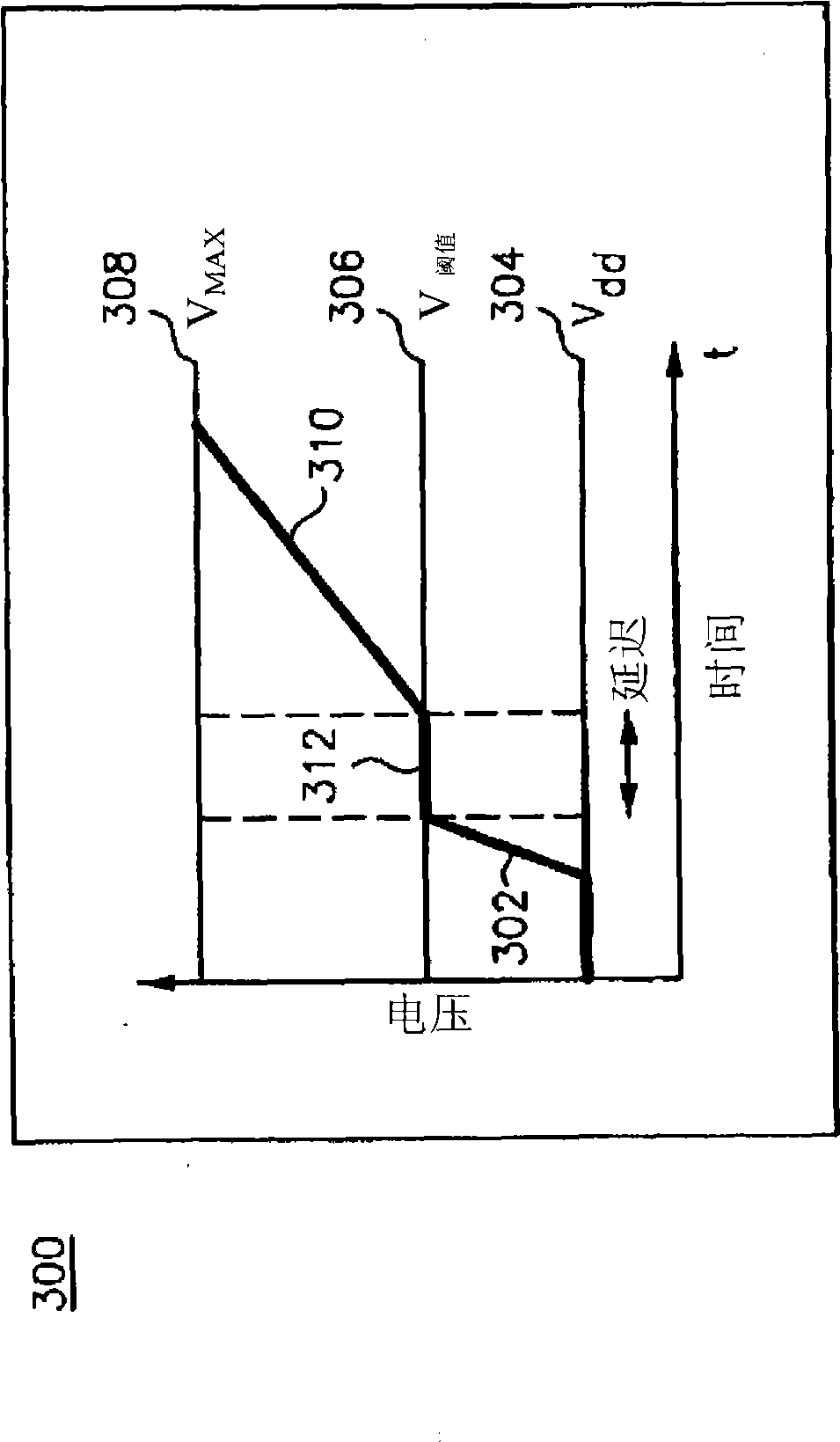
[0019] image 3 is a graphical illustration of a signal waveform (eg, a message signal)...


PUM


Abstract

An apparatus and method for improving memory cell reliability is disclosed. The slew rate is reduced in an applied voltage signal used to program a memory cell when Fowler-Nordheim (FN) tunneling injection is detected. The applied programming signal is provided by a charge pump that is preferably a regulated charge pump. The charge pump is selectively controlled by a slew rate control circuit when FN tunneling injection is detected by a voltage level detection circuit at a predetermined threshold voltage level.

Description

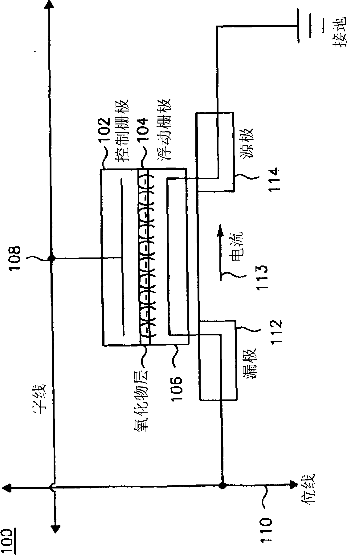
technical field [0001] The present invention relates to an apparatus and method for adaptively controlling slew rate in a memory device using a regulated charge pump. In particular, the present invention relates to improving the reliability and useful life of memory devices by selectively controlling the voltage and waveforms applied to the memory devices during programming. Background technique [0002] A memory device (eg, non-volatile memory) is composed of a plurality of memory cells. FIG. 1 is an example of a conventional memory cell 100 . The memory cell 100 includes a control gate 102 adjacent to an oxide layer 104 , and a floating gate 106 . Fowler-Nordheim (FN) tunneling (also known as field emission) is the process used to program memory cell 100 . In FN tunneling, a high voltage level is applied to control gate 102 via word line 108 . A charge pump may be used to provide the high voltage level to the control gate 102, although any circuit that provides a high ...

Claims


Application Information

Patent Timeline
Patent Type & Authority Applications(China)
IPC IPC(8): H03K5/12
CPCH03K5/01
Inventor 吉米·福特让-米歇尔·达加
Owner ATMEL CORP
Learn More