High-frequency ultrasonic elliptical vibration cutting device
A technology of elliptical vibration and cutting device, which is applied in the direction of auxiliary devices, fluids using vibration, turning equipment, etc., can solve problems such as tool chipping, reduce cutting temperature, improve tool life and machined surface quality, and improve work efficiency. Effect
Inactive Publication Date: 2010-12-01
BEIHANG UNIV
View PDF0 Cites 1 Cited by
- Summary
- Abstract
- Description
- Claims
- Application Information
AI Technical Summary
Problems solved by technology
In order to solve the problem of tool chipping in the cutting process, the present invention proposes an ultrasonic elliptical vibration cutting device at a high frequency of 100kHz to 200kHz
Method used
View moreImage
Smart ImageViewing Examples
Examples
Embodiment Construction
Login to View More PUM
 Abstract
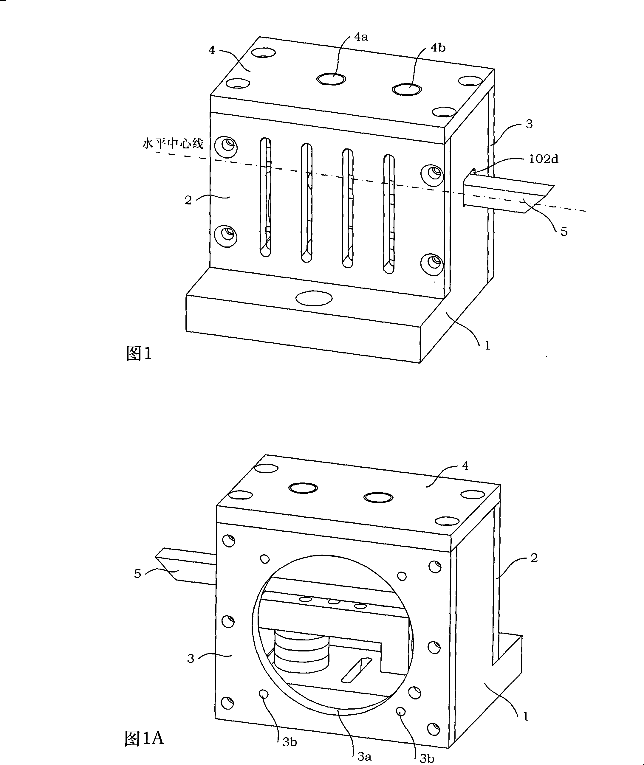
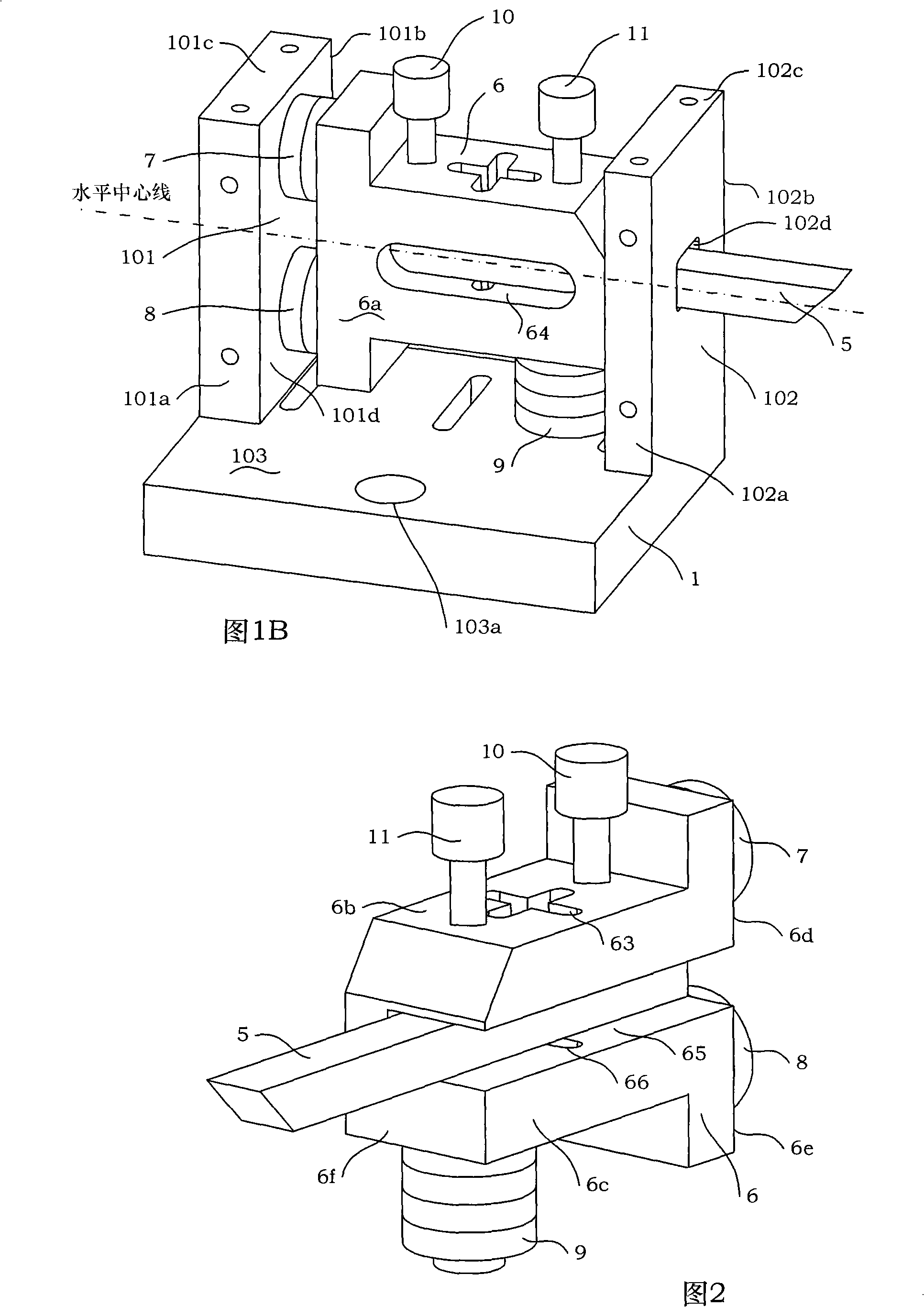
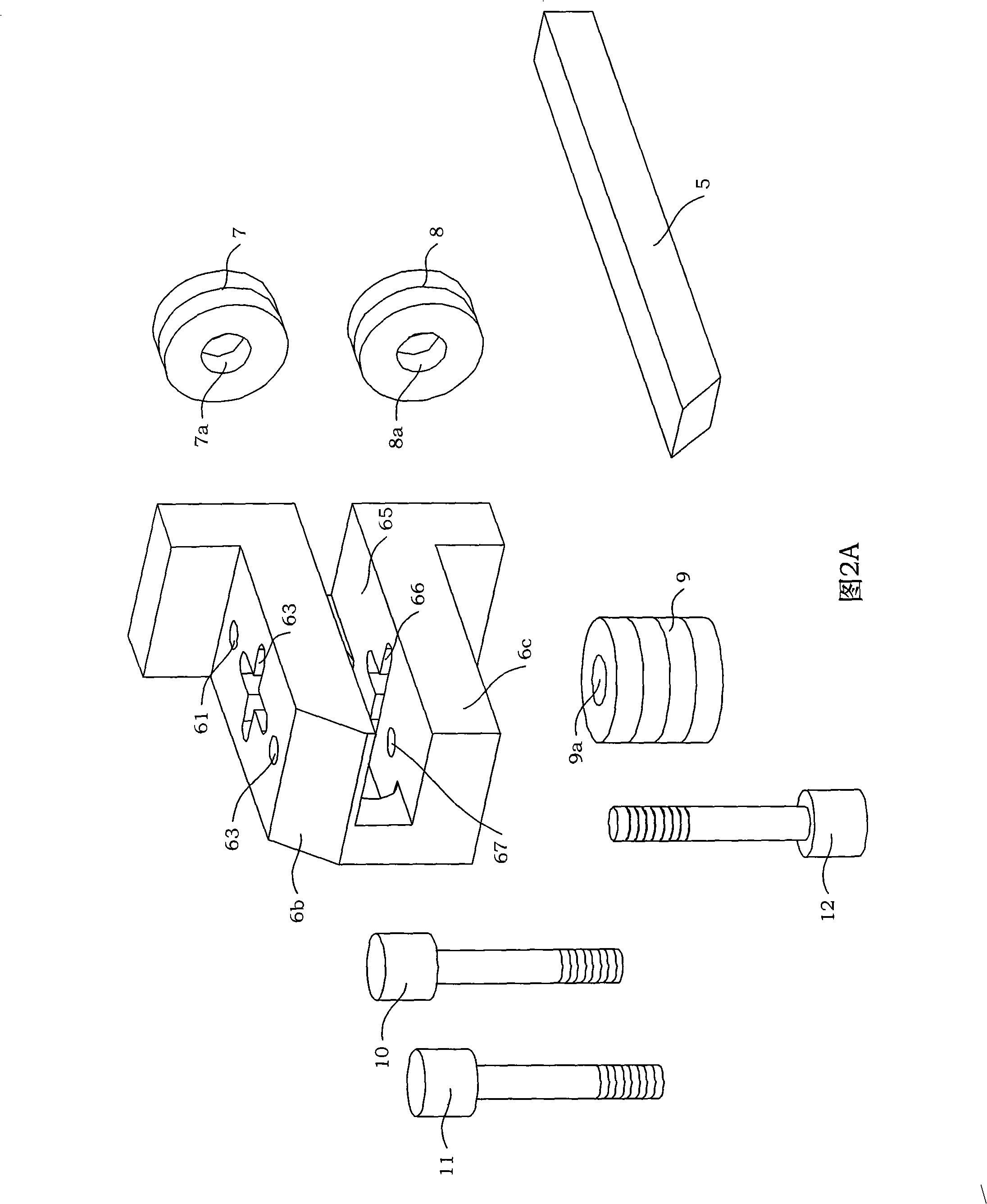
The invention discloses a high frequency ultrasound elliptic vibration cutting device which comprises an ultrasound vibration unit and a casing unit. The ultrasound vibration unit is arranged in the casing unit. The casing unit comprises a base, A cover plate, B cover plate and an upper cover plate. The ultrasound vibration unit comprises an amplitude transformer, a vibrating body, A excitation source, B excitation source and C excitation source. The amplitude transformer is installed on the vibrating body. The end part of the amplitude transformer is provided with a cutting tool. The A excitation source and the B excitation source are arranged in parallel way and are adhered on the lateral side of the vibrating body. The C excitation source is installed on the lower part of the vibratingbody. The A excitation source and the B excitation source form the driving power in horizontal direction. The C excitation source forms the driving power in vertical direction. The phase separation between two mutually vertical high frequency vibrations is applied for compounding an elliptic vibration at the point of the cutting tool. Thus, the processing surface roughness is lowered effectively.The cutting device works at the high vibration frequency of 100 kHz-200 kHz, so that the vibration chipping critical speed of the cutting tool is improved, and the processing efficiency is improved obviously. The amplitude transformer is adopted to be inserted in the vibration body, so that the installation is easy, and the practicality of the ultrasound elliptic vibration cutting can be promoted.
Description
A high-frequency ultrasonic elliptical vibration cutting device technical field The invention relates to a metal cutting processing device used in the field of precision machining, in particular to a cutting device capable of generating high-frequency ultrasonic elliptical vibrations. Background technique Ultrasonic vibration cutting is a cutting method that adds an ultrasonic vibration to the tool to make the original continuous cutting process become intermittent and intermittent, and has a special cutting effect. It was first proposed by Japanese scholars. Ultrasonic vibration cutting has the unique advantages of reducing cutting force and cutting temperature, improving surface quality and shape and position accuracy. However, in the conventional ultrasonic vibration (vibration direction is linear motion) cutting process, when the tool is separated from the workpiece, the flank will hit the machined surface and cause friction, which will not only damage the machined sur...
Claims
Login to View More Application Information
Patent Timeline
 Patent Type & Authority Patents(China)
IPC IPC(8): B26D7/26B06B3/02B06B1/06B23B25/00
Inventor 张德远王桂林李文姜兴刚
Owner BEIHANG UNIV
Features
- R&D
- Intellectual Property
- Life Sciences
- Materials
- Tech Scout
- Unparalleled Data Quality
- Higher Quality Content
- 60% Fewer Hallucinations
Learn More Browse by: Latest US Patents, China's latest patents, Technical Efficacy Thesaurus, Application Domain, Technology Topic, Popular Technical Reports.
© 2025 PatSnap. All rights reserved.Legal|Privacy policy|Modern Slavery Act Transparency Statement|Sitemap|About US| Contact US: help@patsnap.com


