Full digital time-delay locking loop circuit

A delay-locked loop, all-digital technology, applied in digital memory information, electrical components, static memory, etc.

Inactive Publication Date: 2009-08-12
SOUTHEAST UNIV
View PDF0 Cites 18 Cited by
  • Summary
  • Abstract
  • Description
  • Claims
  • Application Information

AI Technical Summary

Problems solved by technology

However, with the increase of the clock frequency of the DDR controller interface, the problem of large intrinsic delay of the numerical control delay line of the equal delay strategy limits the improvement of the operating frequency of the all-digital delay-locked loop.

Method used


Image

  • Full digital time-delay locking loop circuit
  • Full digital time-delay locking loop circuit
  • Full digital time-delay locking loop circuit

Examples


Embodiment Construction

[0022] Below in conjunction with accompanying drawing, the technical scheme of invention is described in detail:

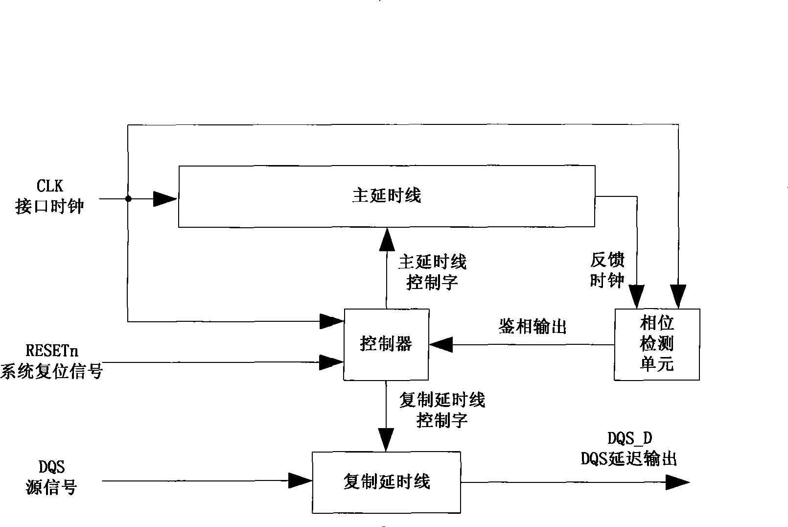
[0023] Such as figure 1 A system block diagram of an all-digital delay-locked loop is shown. In the figure, CLK is input to the main delay line, and the output of the main delay line is named the feedback clock. CLK and the feedback clock perform phase detection, and the controller samples the result of the phase comparison, adjusts the main delay line and the copy delay control word, respectively Control the two delay lines to produce the appropriate amount of delay. The main delay line is responsible for locking the CLK cycle, and the copy delay line is responsible for DQS phase shifting. Phase detection usually includes two links of coarse phase detection and fine phase detection, therefore, the controller also includes a coarse adjustment controller and a fine adjustment controller.

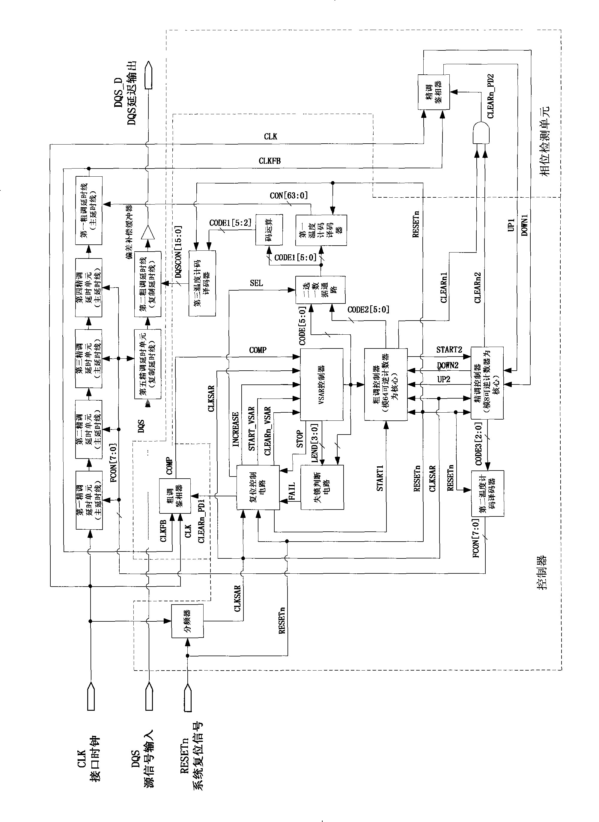
[0024] Such as figure 2 Shown is the complete circuit block diagram of ...


PUM


Abstract

The invention discloses a full digital time delay locking ring circuit, which comprises a main time delay wire, a controller, a phase detection unit and a duplicate time delay wire, wherein a clock interface of the main time delay wire is connected with a clock interface of the controller and a clock interface of the phase detection unit respectively; a feedback clock interface of the main time delay wire is connected with another clock interface of the phase detection unit; an output end of the phase detection unit is connected with an input end of the controller; and an output end of the controller is connected with an input end of the main time delay wire and an input end of the duplicate time delay wire respectively. The full digital time delay locking ring circuit widens the operating frequency range and improves the compatibility with a DDR controller.

Description

technical field [0001] The invention relates to an all-digital delay-locked loop circuit, which belongs to the technical field of delaying DQS signals in a DDR controller. Background technique [0002] The delay locked loop is an important auxiliary calibration design of the DDR controller, which is used to effectively delay the data selection pulse (DQS) signal to ensure the correct sampling of the data by the input register of the DDR controller. The delay-locked loop of the DDR controller does not change the clock frequency, but only generates a delay and inserts it into the DQS signal receiving path. The delay is related to the clock frequency of the DDR controller interface, and the delay deviation must be controlled within a certain percentage of the interface clock cycle. . [0003] In the existing design, the delay-locked loop of the charge pump is a digital-analog hybrid circuit, and there is a problem of compatibility with the digital circuit of the DDR controller...

Claims


Application Information

Patent Timeline
Patent Type & Authority Applications(China)
IPC IPC(8): G11C7/10H03L7/089
Inventor 杨军鲁顺刘新宁时龙兴
Owner SOUTHEAST UNIV
Why Eureka
Try Eureka