Optical power adjusting, measuring method and apparatus
A technology of optical power and commissioning, which is applied in the field of optical networks, can solve problems such as the impact of optical fiber transmission work, achieve good service signal transmission quality, accurate optical power commissioning, and reduce commissioning time.
- Summary
- Abstract
- Description
- Claims
- Application Information
AI Technical Summary
Problems solved by technology
Method used
Image

Examples
Embodiment 1
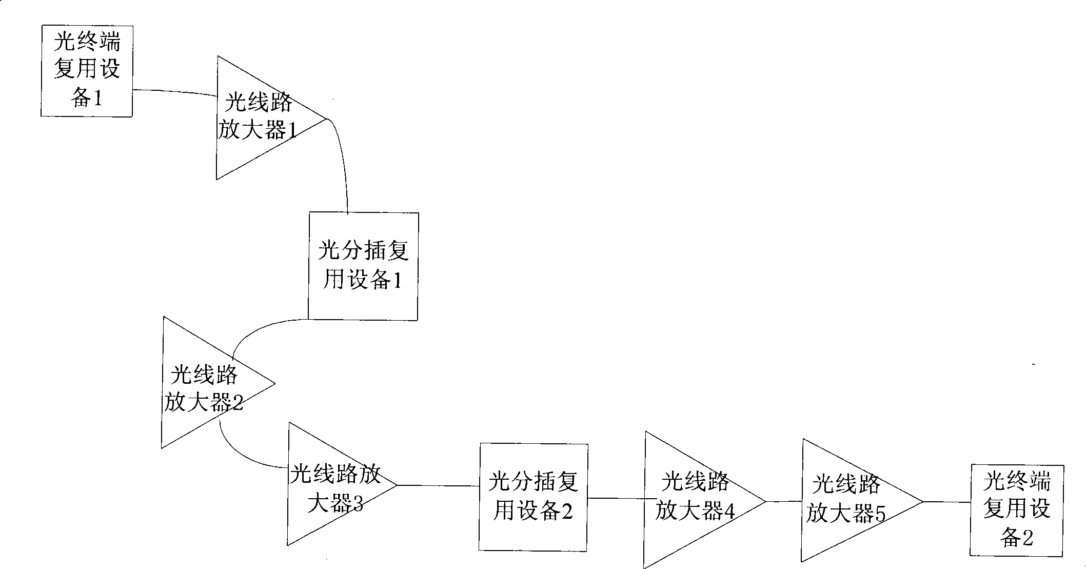
[0031] like image 3 Shown is a schematic diagram of a link of a wavelength division network. In the figure, a link is taken as an example. After the OTM1 (Optical Terminal Multiplexer, optical terminal multiplexer) multiplexes the uplink optical signals generated by the laser, it passes through the OLA1 (Optical Line Multiplexer). Amplifier, optical line amplifier) amplifies and transmits downstream; OADM1 (Optical Add and Drop Multiplexer, optical add-drop multiplexer) receives the optical signal amplified by OLA1, drops the optical signal from OTM1, and then multiplexes the OADM1 itself After the optical signal received from OADM1 is transmitted downstream, it is amplified by OLA2 and OLA3 and then sent to OADM2 for transmission. OADM2 will down-wave the received optical signal from OADM1, and then multiplex the uplink optical signal of OADM2 itself, and then transmit it downstream. , amplified by OLA4 and OLA5 and sent to OTM2. Among them, each OTM, OADM, and OLA in the...
Embodiment 2
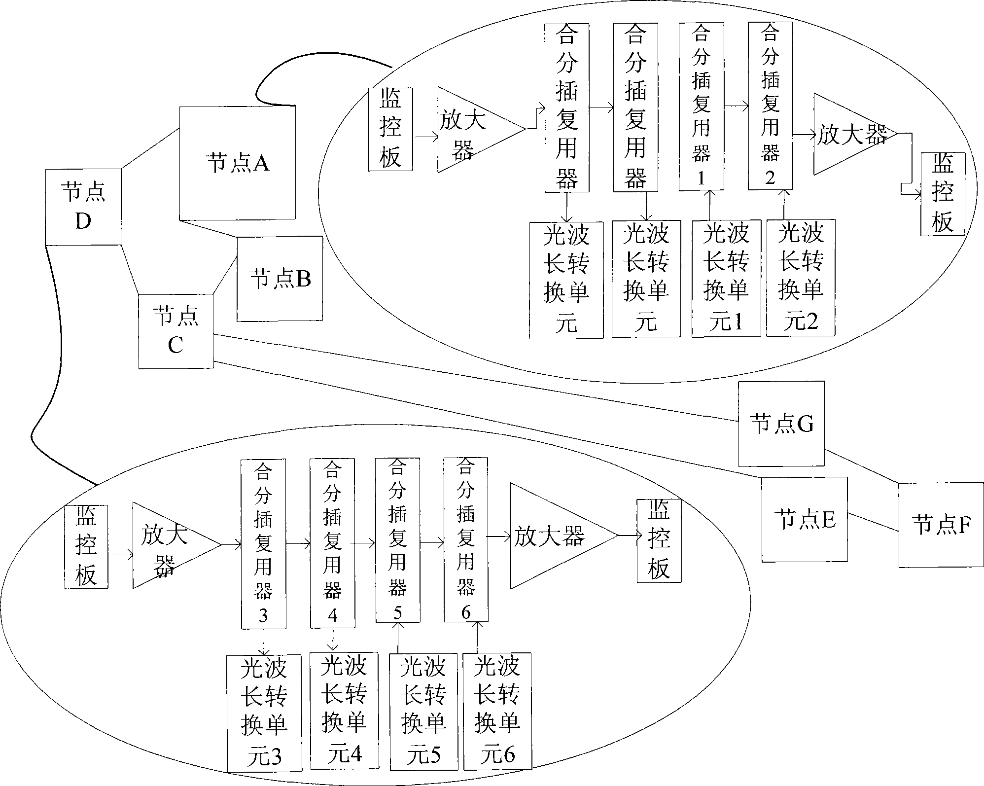
[0099] The technical solution of Embodiment 1 is a detailed description of the optical power adjustment method for the chain network. In this embodiment, a method for adjusting optical power is proposed for the circumstance of a ring network. According to the characteristics of the ring network, the method provided by this embodiment is described in detail, and the contents are as follows:
[0100] For the automatic commissioning of optical power in the WDM network of the ring network, the transmitters of the ring network are all transmitters with through waves. In order to optimize the commissioning effect, the ring network needs to be commissioned twice. Among them, the first commissioning is performed. When , the attenuation value of the punch-through wave obtained according to the calibration attenuation formula cannot be changed, so a second commissioning is required to optimize the total power of the combined wave to make up for the error caused by the calculation accord...
Embodiment 3
[0113] The embodiment of the present invention provides a device for optical power commissioning, such as Figure 8 As shown, the equipment includes:
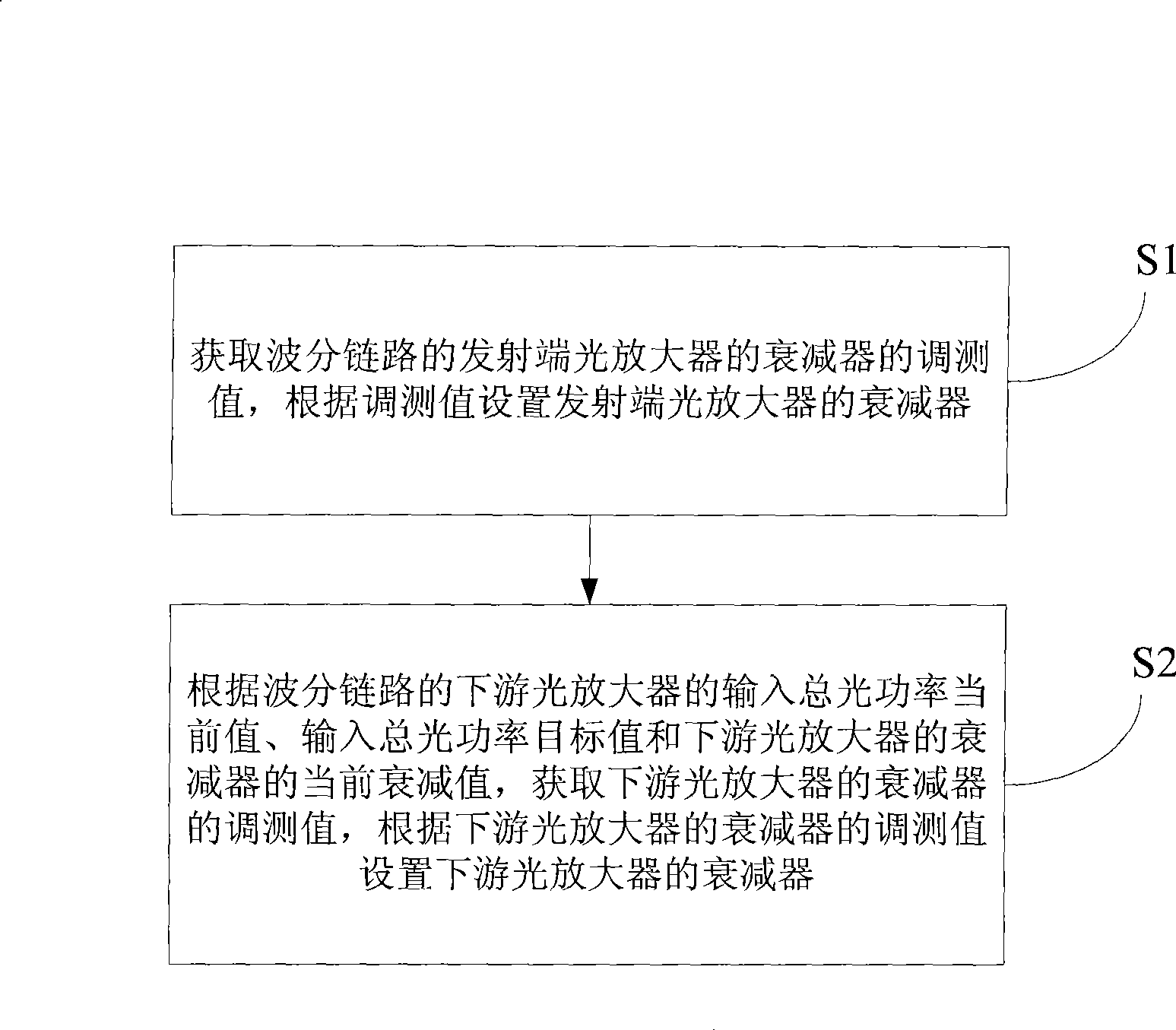
[0114] a first acquisition module, configured to acquire the commissioning value of the attenuator of the optical amplifier at the transmitting end of the wavelength division link;
[0115] a first setting module, configured to set the attenuator of the optical amplifier at the transmitting end according to the commissioning value obtained by the first obtaining module;
[0116] The second acquisition module is configured to, after the first setting module sets the attenuator of the optical amplifier at the transmitting end, according to the current value of the total input optical power of the downstream optical amplifier of the wavelength division link, the target value of the total input optical power and the output value of the downstream optical amplifier. The current attenuation value of the attenuator, to obtain the adj...
PUM
 Abstract
Description
Claims
Application Information
 - R&D
- Intellectual Property
- Life Sciences
- Materials
- Tech Scout
- Unparalleled Data Quality
- Higher Quality Content
- 60% Fewer Hallucinations
Browse by: Latest US Patents, China's latest patents, Technical Efficacy Thesaurus, Application Domain, Technology Topic, Popular Technical Reports.
© 2025 PatSnap. All rights reserved.Legal|Privacy policy|Modern Slavery Act Transparency Statement|Sitemap|About US| Contact US: help@patsnap.com