Image processing device for medical use and image processing method for medical use

An image processing device and image processing technology, applied in image data processing, image data processing, image enhancement and other directions, can solve the problems of decreased detection accuracy and no proposal for appropriate changes in lesion detection benchmarks.

Active Publication Date: 2009-08-12
OLYMPUS CORP
View PDF3 Cites 20 Cited by
  • Summary
  • Abstract
  • Description
  • Claims
  • Application Information

AI Technical Summary

Problems solved by technology

However, in the image processing method of Japanese Patent Application Laid-Open No. 2005-192880, there is no proposal for appropriately changing the lesion detection criterion according to the dens

Method used


Image

  • Image processing device for medical use and image processing method for medical use
  • Image processing device for medical use and image processing method for medical use
  • Image processing device for medical use and image processing method for medical use

Examples


no. 1 approach

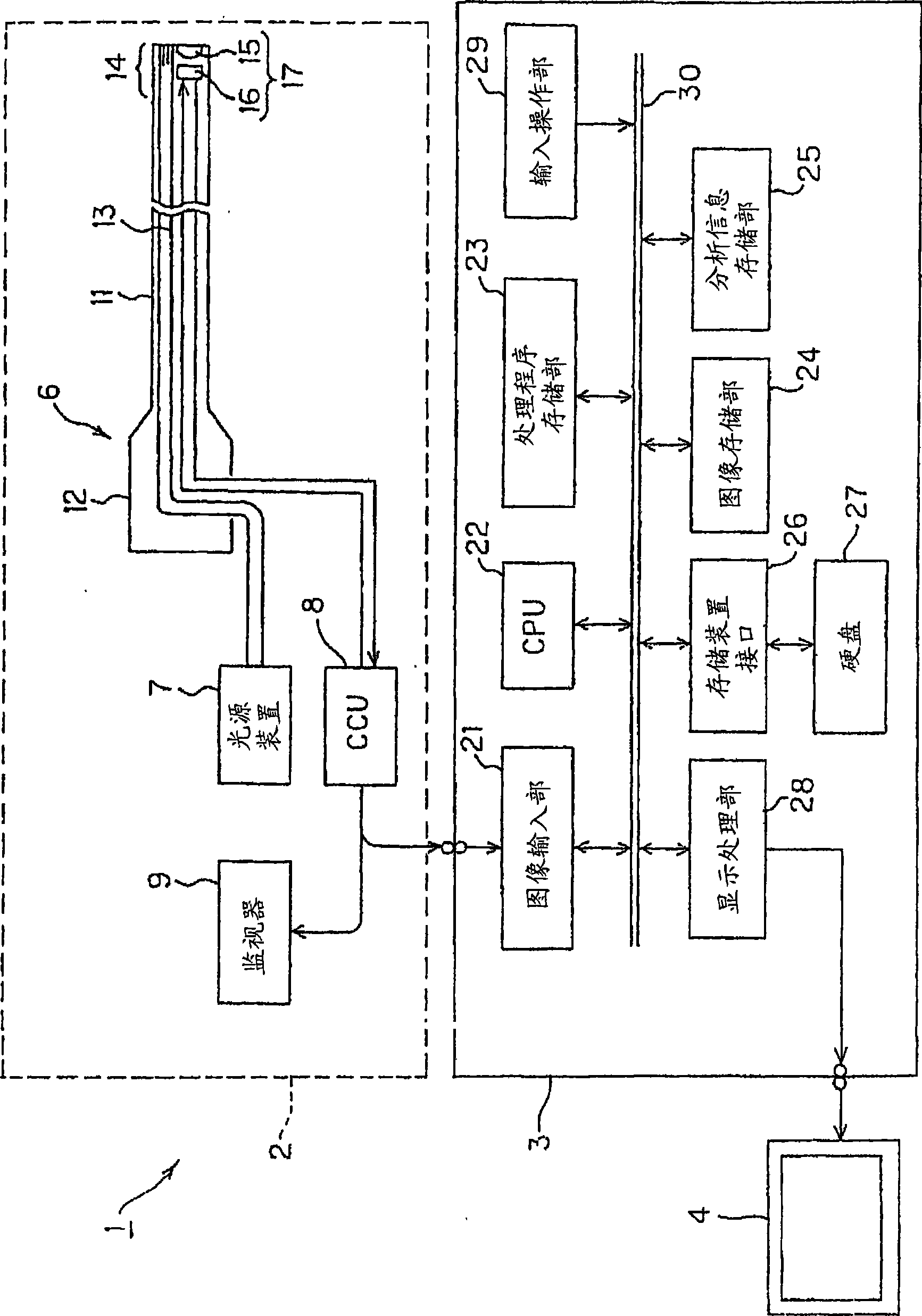
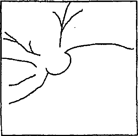
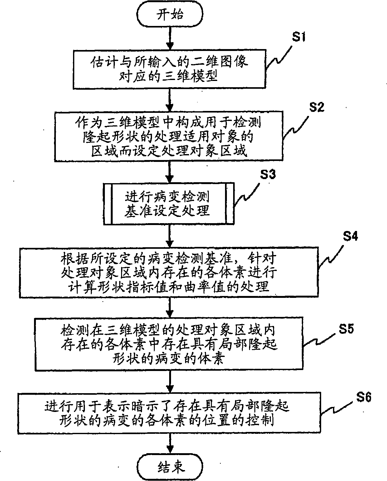
[0044] Figure 1 to Figure 7 It relates to the first embodiment of the present invention. figure 1 It is a diagram showing an example of the overall configuration of an endoscope system using the medical image processing apparatus according to the embodiment of the present invention. figure 2 is shown by figure 1 A diagram showing an example of a two-dimensional image of an image of a subject captured by the endoscope system. image 3 is showing figure 1 A flowchart of the procedure of processing performed by the medical image processing apparatus in the first embodiment. Figure 4 is as image 3 A flowchart showing an example of the processing performed in the first embodiment is shown as the lesion detection standard setting processing in FIG. Figure 5 is shown in figure 2 A diagram showing an example of a processing result when the shown two-dimensional image is divided into a plurality of regions. Image 6 is shown for figure 1 The 3D model estimated by the medi...

no. 2 approach

[0088] Figure 8 to Figure 22 It relates to the second embodiment of the present invention. Figure 8 is as image 3 A flow chart showing an example of processing performed in the second embodiment is shown as the lesion detection standard setting processing in FIG. Figure 9 is showing Figure 8 A flowchart of an example of 2D image segmentation processing in . Figure 10 is showing Figure 9 A diagram of an example of a 2D image used in the processing. Figure 11 is shown by Figure 9 A diagram of an example of processing detected edges. Figure 12 is shown by Figure 9 The processing of the detected edges with Figure 11 Diagrams of different examples. Figure 13 is shown based on Figure 12 The edge of the Figure 11 A graph of the state of each edge of . Figure 14 is shown in the pass Figure 9 processing of Figure 10 A diagram of the processing results when the two-dimensional image is segmented. Figure 15 is showing Figure 8 2D image segmentation pro...

no. 3 approach

[0125] Figure 23 to Figure 27 It relates to the third embodiment of the present invention. Figure 23 is showing figure 1 A flowchart of the processing procedure performed by the medical image processing apparatus in the third embodiment. Figure 24 is as Figure 23 A flow chart showing an example of processing performed in the third embodiment is shown as the lesion detection standard setting processing in FIG. Figure 25 is shown in Figure 24 A graph of the correlation between the distance LH and the weight coefficient ω calculated in the processing of . Figure 26 is as Figure 23 The difference between the processing performed in the third embodiment and the lesion detection standard setting processing in Figure 24 Flowcharts of different examples. Figure 27 is shown by Figure 26 A map of the region detected as the edge portion of the two-dimensional image by the processing.

[0126] In addition, a detailed description of parts having the same configuration a...


PUM


Abstract

A medical image processing apparatus of the present invention includes: a three-dimensional model estimating section for estimating a three-dimensional model of an object based on a two-dimensional image of an image of the object which is inputted from a medical image pickup apparatus; an image dividing section for dividing the two-dimensional image into a plurality of regions each of which includes at least one or more pixels; a feature value calculation section for calculating a feature value according to a grayscale of each pixel in one region for each of the plurality of regions; and a lesion detection reference setting section for setting lesion detection reference for detecting a locally protruding lesion in the regions of the three-dimensional model which correspond to each of the plurality of regions, based on the feature value according to the grayscale.

Description

technical field [0001] The present invention relates to a medical image processing device and a medical image processing method, and more particularly to a medical image processing device and a medical image processing method capable of detecting a lesion having a locally raised shape. Background technique [0002] Conventionally, in the medical field, observations using imaging equipment such as X-ray diagnostic equipment, CT, MRI, ultrasonic observation equipment, and endoscope equipment have been widely performed. The endoscope device in this kind of image capture equipment has, for example, an insertion portion that can be inserted into a body cavity, and has such a function and structure: use an imaging unit such as a solid-state imaging device to scan the object lens that passes through the front end of the insertion portion. The image in the body cavity formed by the optical system is captured and output as an imaging signal, and an image of the image in the body cavi...

Claims


Application Information

Patent Timeline
IPC IPC(8): A61B1/04G06T1/00
CPCG06T2207/20132G06T2207/10016G06T7/403G06T2207/30032G06T2207/10068G06T2207/20021G06T7/0085G06T2200/04A61B1/042G06T7/0053G06T2207/20136G06T7/0012G06T7/507G06T7/13G06T7/44G06T7/181
Inventor 沢美穗西村博一田中秀树井上凉子中村健次
Owner OLYMPUS CORP
Why Eureka
Try Eureka