Fan drive system

A driving system and fan technology, which is applied in fluid pressure actuated system components, engine components, engine cooling, etc., can solve the problems of increasing the number of hydraulic pumps, a large amount of installation space, and high cost, so as to reduce the pump capacity, The effect of preventing waste and stabilizing operation

Inactive Publication Date: 2009-08-12
KOMATSU LTD
View PDF5 Cites 4 Cited by
  • Summary
  • Abstract
  • Description
  • Claims
  • Application Information

AI Technical Summary

Problems solved by technology

However, it is necessary to relocate the hydraulic pump dedicated to the cooling fan, so as a whole, the number of hydraulic pumps increases
[0006] Furthermore, in order to relocate the hydraulic pump, the design structure becomes complicated and a large amount of installation space is required
In addition, the cost increases and the number of parts increases.

Method used


Image

  • Fan drive system
  • Fan drive system
  • Fan drive system

Examples


Embodiment 1

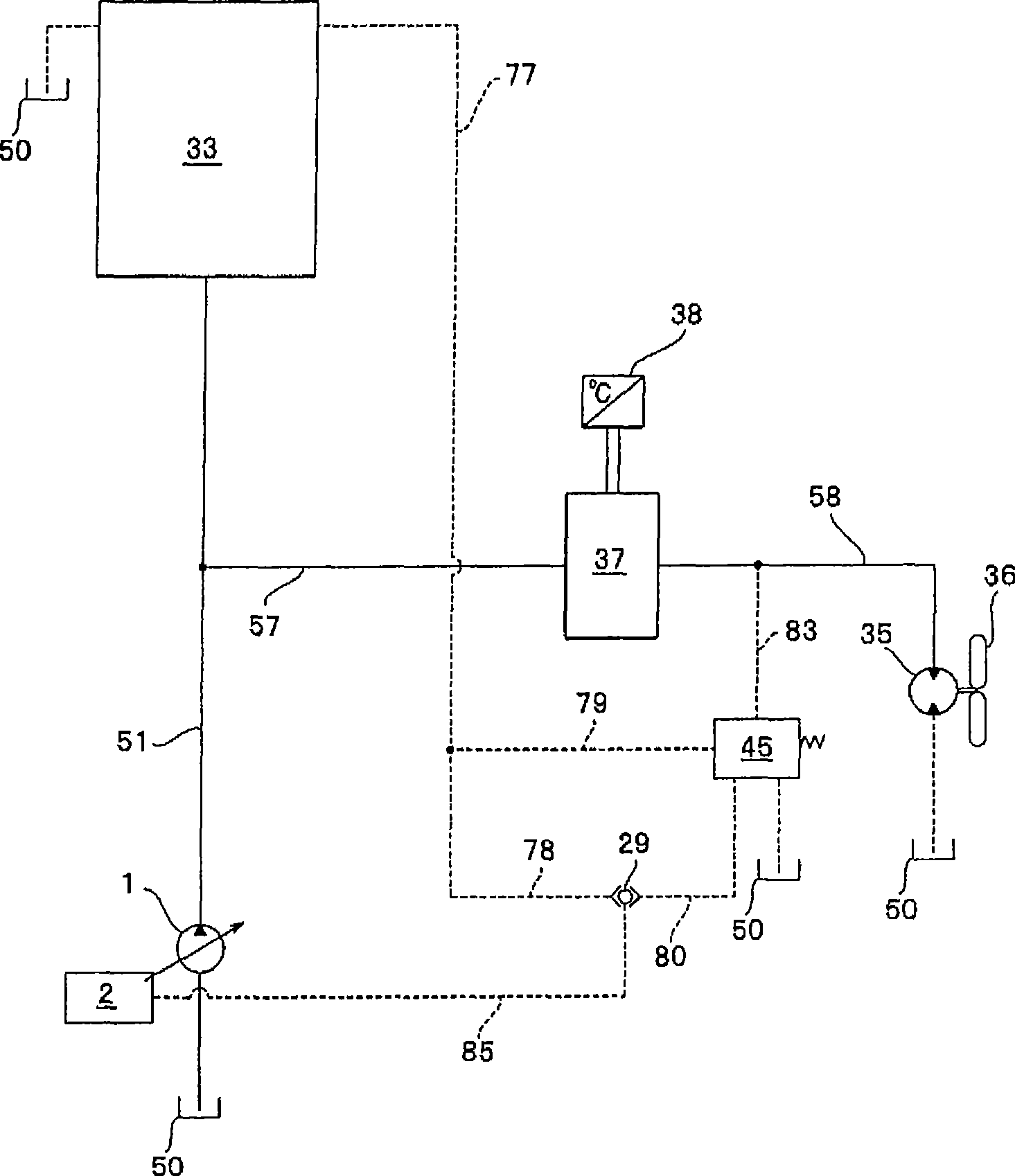
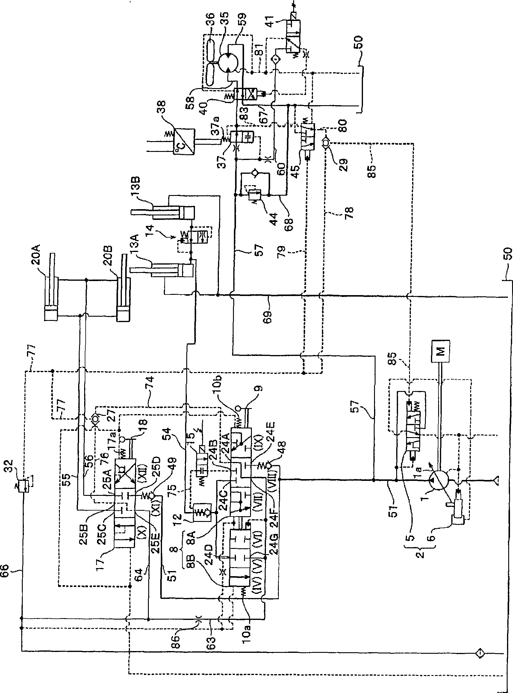
[0056] use figure 1 and figure 2 , the hydraulic circuit including the fan drive system according to the first embodiment of the present invention will be described. figure 1 A simplified hydraulic circuit diagram is shown in, figure 2 A detailed hydraulic circuit diagram is shown in . First, use figure 1 , briefly explaining the hydraulic circuit of the fan driving system according to the first embodiment of the present invention, and then using figure 2 , the hydraulic circuit including the fan drive system according to the first embodiment of the present invention will be described. Also, in figure 1 and figure 2 Common part numbers are described using the same part number.

[0057] like figure 1 As shown, the discharge flow rate from the load pressure sensitive variable displacement pump 1 driven by an engine not shown is discharged to the discharge oil passage 51 which is the first discharge oil passage. The discharge oil passage 51 branches off from an ...

Embodiment 2

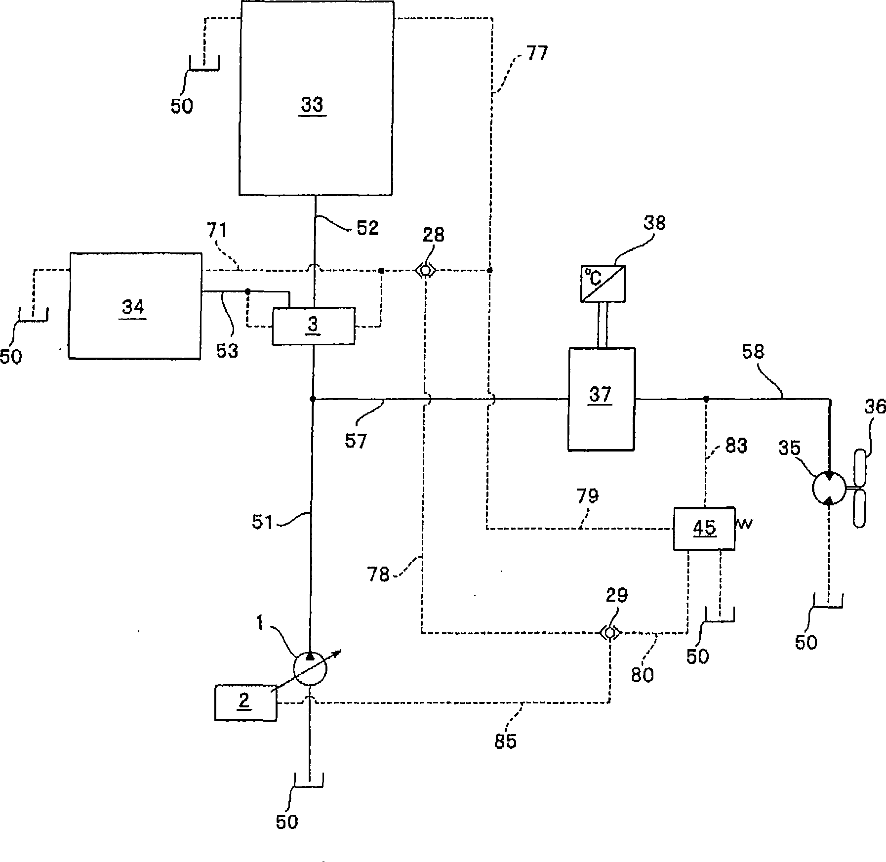
[0122] use image 3 and Figure 4 , will describe a hydraulic circuit diagram of a fan drive system according to a second embodiment of the present invention. In the second embodiment, in addition to the hydraulic circuit configuration of the first embodiment, a circuit configuration in which a steering drive circuit is added is formed. In addition, as the load pressure in the hydraulic control oil passage 78 as the first hydraulic control oil passage led to the shuttle valve 29, each of the steering drive unit 30, the lift cylinders 13A, 13B, and the dump cylinders 20A, 20B is used. The highest load pressure among load pressures. In this structure, Example 2 is formed as a structure different from that of Example 1, but other structures are formed as the same structures as those in Example 1.

[0123] Therefore, among the configurations of the second embodiment, the same components as those of the first embodiment are assigned the same reference numerals as those used in t...

Embodiment 3

[0158] Figure 5 , Image 6Each of the drawings shows a hydraulic circuit diagram of a fan drive system including a third embodiment of the present invention. In Embodiment 3 and Embodiment 1 or Embodiment 2, the circuit structure in Embodiment 3 is different from that in Embodiment 1 and Embodiment 2 regarding the circuit structure for guiding the load pressure to the hydraulic control oil passage 80 . other structures in Figure 5 Formed as the loop structure as the embodiment 1 figure 2 The same loop structure, in Image 6 Formed as the loop structure as the embodiment 2 Figure 4 same loop structure.

[0159] Therefore, in the non-configured priority valve 3 Figure 5 In FIG. 2 , for the same structure as in Embodiment 1, description thereof is omitted by using the same part numbers as those used in Embodiment 1. FIG. In addition, when using the priority valve 3 Image 6 In , for the same structure as in Embodiment 2, description thereof is omitted by using the sa...


PUM


Abstract

A flow rate control valve (37) controlled based on coolant temperature is placed in an oil path for supplying oil to a hydraulic motor (35) from a variable displacement pump (1) in which the swash plate angle is controlled by a displacement control device (2). A pilot oil path (83) for detecting load pressure of the hydraulic motor (35) is connected to a shuttle valve (29) via a load pressure separation valve (45). To the shuttle valve (29) are led a maximum load pressure in a working machine circuit (33) and load pressure in a pilot oil path (80). High-pressure-side load pressure selected by the shuttle valve (29) is led to the displacement control device (2) via a pilot oil path (85). The load pressure separation valve (45) is controlled by load pressure from a pilot oil path (79). When load pressure is generated in the working machine, the load pressure separation valve (45) shuts off the communication between the pilot oil path (83) and the shuttle valve (29) to supply tank pressure to the shuttle valve (29).

Description

technical field [0001] The present invention relates to a fan drive system mounted on a work machine such as a forklift, a skid steer loader (SSL), a crawler dump truck, etc., and drives an engine cooling fan. Background technique [0002] Conventionally, in working machines, a water-cooled cooling device has been used to cool an engine. That is, it is configured to cool the engine by circulating a cooling medium (cooling water) through a water jacket provided in the engine main body. The cooling medium heated in the water jacket is led to the radiator to be cooled, and the cooled cooling medium returns to the water jacket again. [0003] A cooling fan is arranged in front of the radiator, and the cooling medium passing through the radiator is cooled by wind generated by the cooling fan. Usually, the cooling fan is formed as a belt-driven structure under the action of the engine. Therefore, the rotation speed of the cooling fan becomes a rotation speed corresponding to th...

Claims


Application Information

Patent Timeline
Patent Type & Authority Applications(China)
IPC IPC(8): F01P7/04E02F9/00E02F9/22F15B11/00F15B21/04
CPCF15B2211/6054E02F9/2232F15B11/168F15B11/05F15B2211/20523F15B2211/7058F15B11/165E02F9/2296F15B2211/40553F15B2211/20553F01P7/044E02F9/2228E02F9/2203E02F9/225F15B2211/6343F15B2211/654
Inventor 片冈丰美福岛纯一丸田和弘石崎直树
Owner KOMATSU LTD
Why Eureka
Try Eureka