Laser scanner

A laser scanner and laser source technology, applied in the field of laser scanners, can solve problems such as complex rotating joints and easy failures

Active Publication Date: 2009-08-12
LEICA GEOSYSTEMS AG
View PDF3 Cites 33 Cited by
  • Summary
  • Abstract
  • Description
  • Claims
  • Application Information

AI Technical Summary

Problems solved by technology

Known swivel joints are complex and prone to failure when the device is used in harsh conditions

Method used


Image

  • Laser scanner
  • Laser scanner
  • Laser scanner

Examples


Embodiment Construction

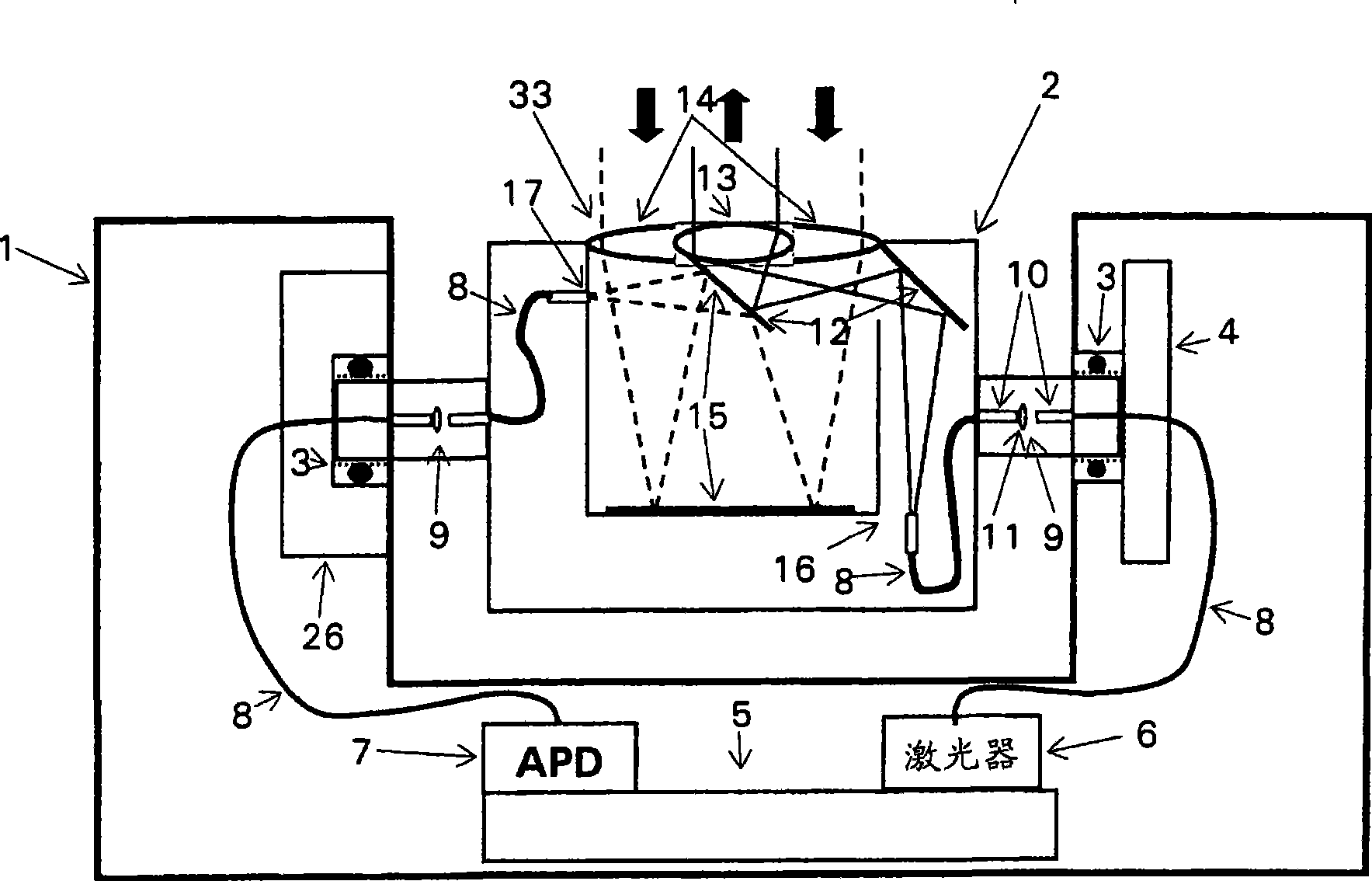
[0029] figure 1 A rotor 1 is shown in which a rotating body 2 is mounted on a rotating bearing 3 so as to be rotatable about a horizontal axis. The rotor 1 can be moved about a vertical axis by means of a first rotary drive not shown here, so that the rotational position can be determined by means of a first angle measuring device. The rotary body 2 is rotated by the second rotary driver 26 . The rotational position of the rotating body 2 is detected by means of the second angle measuring device 4 . The evaluation electronics 5 in the rotor 1 are connected to a laser source 6 (laser) and a laser detector 7 (APD) of the distance measuring device.

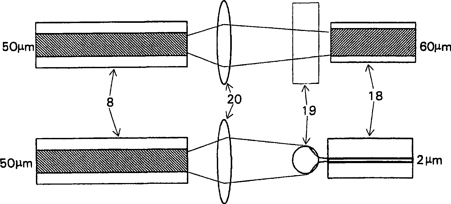
[0030] The laser light emitted from the laser 6 is sent from the laser source 6 to the optical link 9 between the rotor 1 and the rotating body 2 through the waveguide 8 in the rotor. A multimode fiber having a core diameter of, for example, 50 μm and a numerical aperture of, for example, 0.12 is suitable for this purpose.

[003...


PUM


Abstract

A laser scanner for detecting spatial surroundings comprises a stator (21), a rotor (1), mounted on the stator (21) to be rotatable about a first rotational axis, and a rotary body (2), mounted on the rotor (1) to be rotatable about a second rotational axis. A laser source (6) and a detector (7) are arranged in the rotor (1). One optical link (9) each is configured on the second rotational axis on every side of the rotary body (2) between the rotor (1) and the rotary body (2) so that emission light can be introduced by the laser source into the rotary body (2) via the first optical link (8) and reception light can be discharge from the rotary body (2) via the second optical link (9). A first rotary drive (25) drives the rotor (21) and a second rotary drive (26) drives the rotary body (2). Two goniometers (4) and evaluation electronics (5) which are connected to the laser source (6) and the detector (7) allow association of a detected distance with a corresponding direction. The rotary body (2) can have a very compact design, is completely passive and therefore does not require any power supply or transmission of signals.

Description

technical field [0001] The invention relates to a laser scanner according to the preamble of claim 1 . Background technique [0002] So-called 3D laser scanners are often used to probe the space environment. These 3D laser scanners are set at a certain position and scan the 3D scene from that position. Here, the measurement process requires rotation about two orthogonal axes, namely about a vertical axis and a horizontal axis rotating about the vertical axis. Rotation about the vertical axis is achieved by moving the rotor around the stator, in which the second axis of rotation is located. [0003] In the embodiment according to EP 1 562 055, the entire transmitting optics and receiving optics are fixedly arranged. A deflection mirror mounted on a rotor so that it can rotate around a horizontal axis is arranged vertically above the transmitting optical system and the receiving optical system. The laser light is sent to the deflection mirror through the emission optical s...

Claims


Application Information

Patent Timeline
Patent Type & Authority Applications(China)
IPC IPC(8): G01S17/42G01S17/89G01C1/02
CPCG02B6/32G01S17/89G02B6/4204G01S17/42G01S7/4818G01S7/4817
Inventor 托马斯·延森克努特·西尔克斯
Owner LEICA GEOSYSTEMS AG
Why Eureka
Try Eureka