Motor drive device

A motor-driven, multi-phase motor technology, used in electrical devices, output power conversion devices, electric vehicles, etc., can solve the problems of thermal damage, high possibility of inverter, and high motor speed

Inactive Publication Date: 2009-08-12
TOYOTA JIDOSHA KK
View PDF1 Cites 21 Cited by
  • Summary
  • Abstract
  • Description
  • Claims
  • Application Information

AI Technical Summary

Problems solved by technology

[0007] However, in the configuration in which all the switching elements of the inverter are turned off as in Japanese Patent Application Laid-Open No. 2004-289903, there is a short-circuit current flowing through the inside of the inverter due to the counter electromotive force generated in the vehicle driving motor when the vehicle is evasive. and the possibility of a wiring harness (W / H), which is the conductive wire connecting the neutral point of the motor and the phases of the converter
Since the counter electromotive force generated by the motor is proportional to the rotation speed of the motor, if the rotation speed of the motor increases, the current exceeding the set current value determined by the heat resistance limit of the switching element and the wiring harness will pass through the inverter and the conductive wire. There is thus a risk of thermal damage to them
[0008] Such a problem may occur especially when the vehicle is towed and transported to a repair shop, etc. after an emergency stop of the vehicle
That is, when the vehicle is towed, the rotation speed of the motor tends to be high and the travel time tends to be relatively long compared to the time of evasive travel in which the power supply to the drive shaft is restricted.
When such a vehicle is towed, since a large back electromotive force is continuously generated in the motor, there is a high possibility that the inverter and the wiring harness will become in an overcurrent state.

Method used


Image

  • Motor drive device
  • Motor drive device
  • Motor drive device

Examples


Embodiment Construction

[0028] Hereinafter, embodiments of the present invention will be described in detail with reference to the drawings. In addition, the same code|symbol in a figure shows the same or a corresponding part.

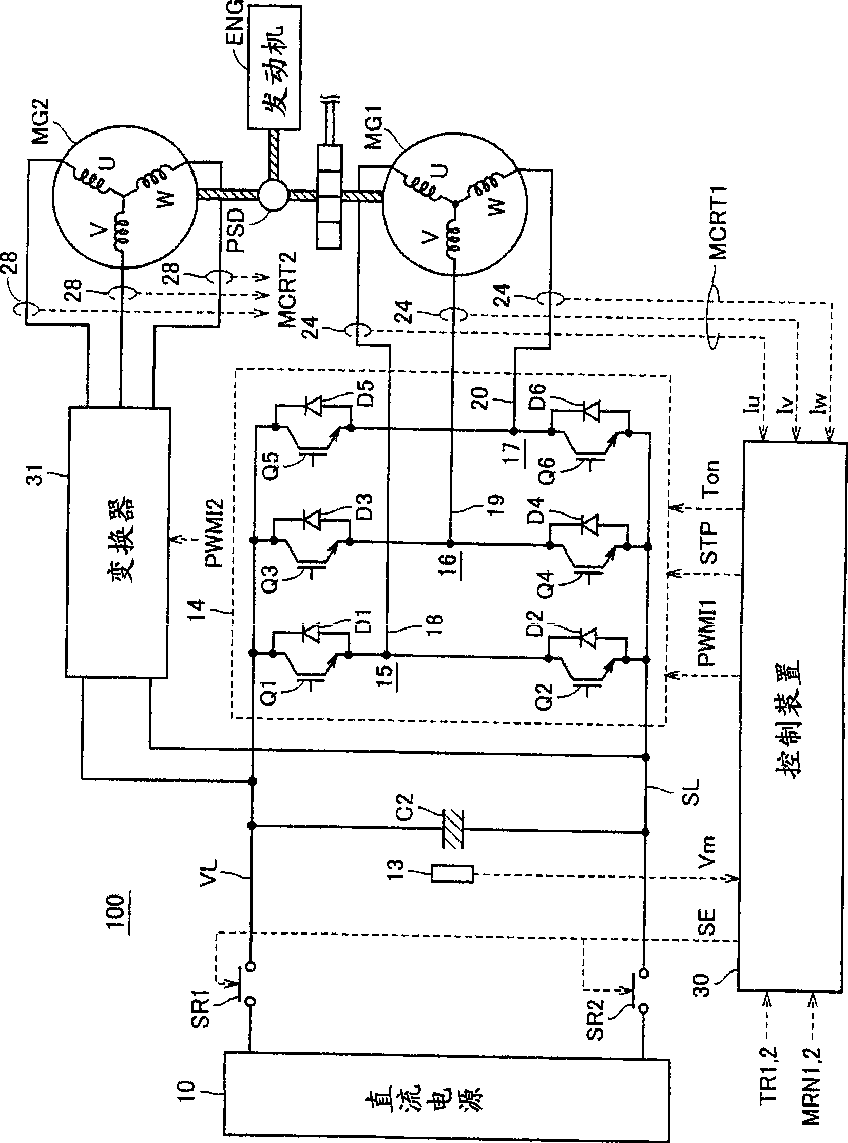
[0029] figure 1 It is a schematic block diagram of the motor drive device concerning embodiment of this invention.

[0030] refer to figure 1 , the motor drive device 100 includes a DC power supply 10 , a voltage sensor 13 , system relays SR1 , SR2 , a capacitor C2 , inverters 14 , 31 , current sensors 24 , 28 , and a control device 30 .

[0031] The engine ENG generates driving force using fuel energy of fuel such as gasoline as an energy source. The driving force generated by the engine ENG, such as figure 1 As shown by the thick oblique line in , it is divided into two paths by the power distribution mechanism PSD. One is a path that is transmitted to a drive shaft that drives the wheels via a reduction gear (not shown). The other is a route for transmission to motor...


PUM


Abstract

A control device (30) judges that an inverter (14) has failed upon detection of an overcurrent in any one of the IGBT elements of the inverter (14) during drive of a motor generator (MG1). The control device (30) stops operation of the inverter (14) in response to the failure judgment and identifies a shortcircuit phase according to a motor current (MCRT1) from the current sensor (24). The control device (30) simultaneously turns ON two IGBT elements constituting an upper and a lower arm of the shortcircuit phase in a discharge process of a capacitor (C2) executed upon stop control of a vehicle. Thus, the two IGBT elements receive excessive shortcircuit current to suddenly increase the thermal loss, which causes a shortcircuit failure. This suppresses the overcurrent of the inverter and the power supply line caused by the electromotive force generated in the motor generator (MG1) when towing a vehicle.

Description

technical field [0001] The present invention relates to a motor drive device, and more particularly, to a motor drive device capable of preventing overheating caused by a short-circuit failure of a power conversion device. Background technique [0002] Recently, hybrid vehicles (Hybrid Vehicles) and electric vehicles (Electric Vehicles) have attracted attention as eco-friendly vehicles. A hybrid vehicle is a vehicle in which a DC power supply, an inverter, and a motor driven by the inverter are used as power sources in addition to conventional engines. That is, a power source is obtained by driving an engine, a DC voltage from a DC power supply is converted into an AC voltage by an inverter, and a motor is rotated by the converted AC voltage to obtain a power source. [0003] In addition, an electric vehicle is a vehicle that uses a DC power supply, an inverter, and a motor driven by the inverter as power sources. [0004] In a motor drive device mounted on such a hybrid v...

Claims


Application Information

Patent Timeline
Patent Type & Authority Applications(China)
IPC IPC(8): H02M7/48
CPCH02P29/021H02P29/028B60L3/003Y02T10/642H02M7/5387H02P29/0241H02P29/032H02M1/322Y02T10/64
Inventor 伊藤雄二
Owner TOYOTA JIDOSHA KK
Why Eureka
Try Eureka