
Self-paralleling front rubber roll apparatus

A front rubber and rubber roller technology, applied in textiles and papermaking, drafting equipment, spinning machines, etc., can solve the problems of uneven fiber pressure, large non-parallelism, increase production costs, etc., to improve yarn quality, The effect of reducing the cost of renovation

Inactive Publication Date: 2009-08-19
SHANGHAI TEXTILE GRP DETECTION STANDARD CO LTD +1
View PDF3 Cites 0 Cited by
  • Summary
  • Abstract
  • Description
  • Claims
  • Application Information

AI Technical Summary

Problems solved by technology

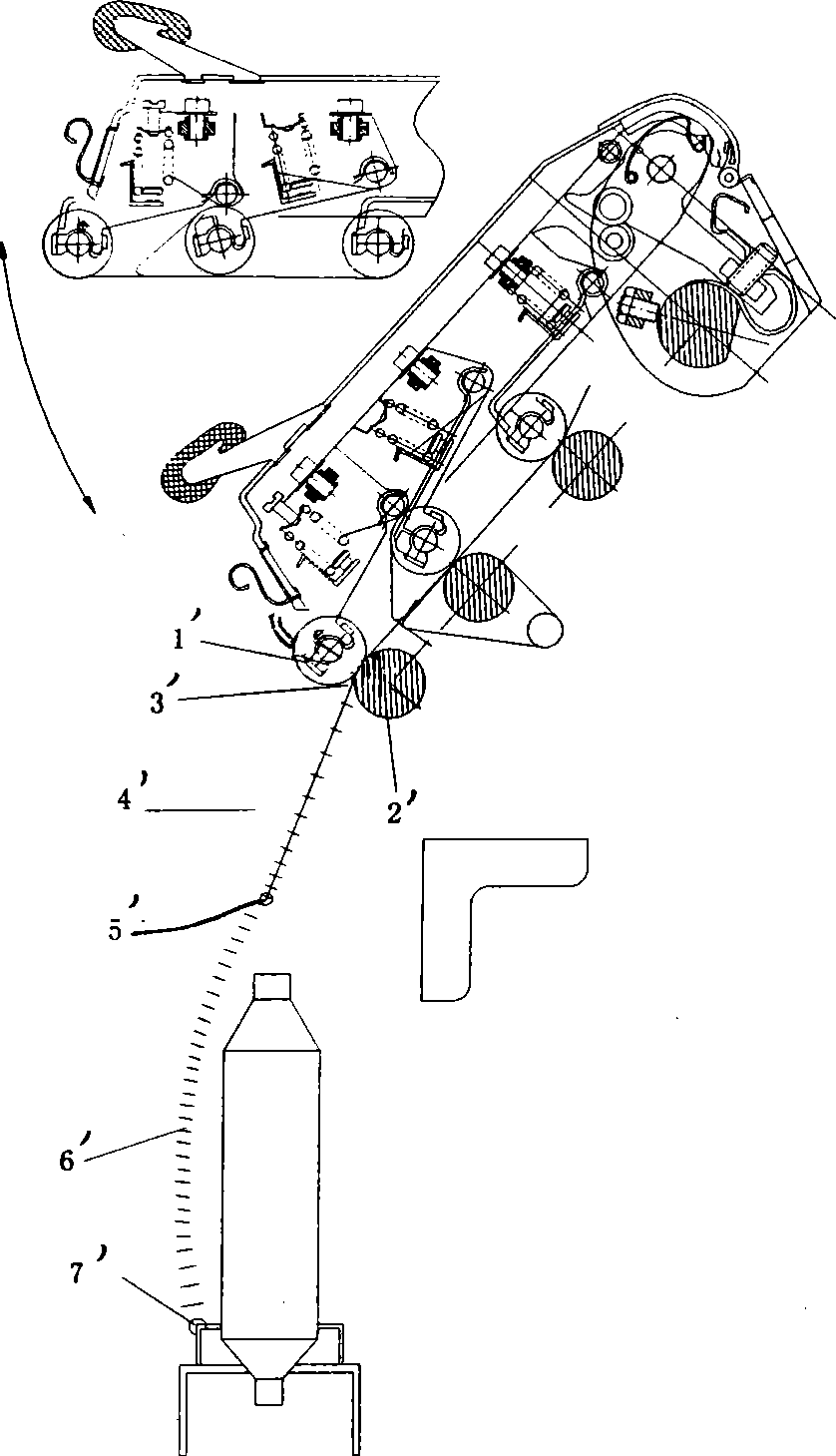
The non-parallelism error between the front rubber roller and the front bottom roller will affect the correct contact position of the roller nip. If the non-parallelism is too large, it will seriously affect the quality indicators such as the evenness of the drafted yarn, the thickness of the yarn, and the hair grain.
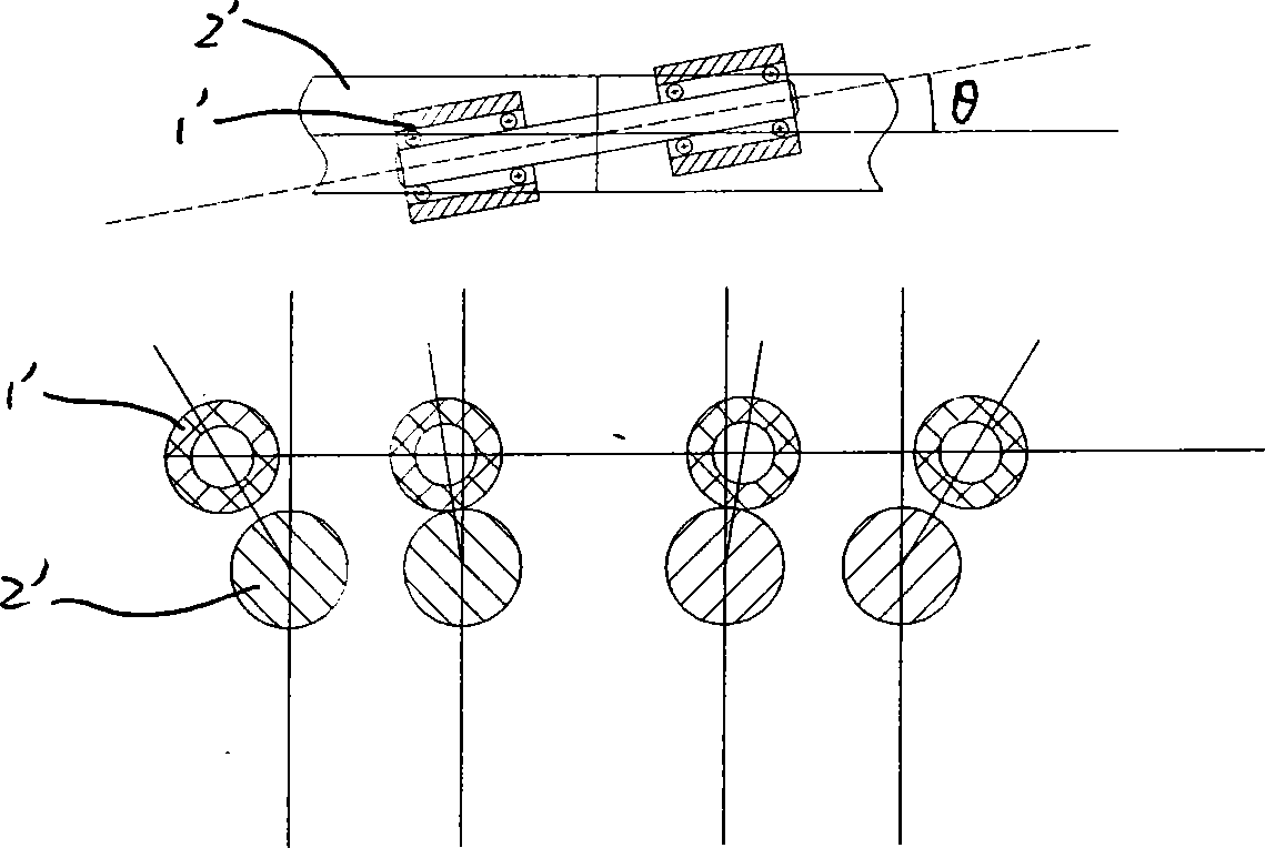
[0004] The non-parallelism error between the rubber roller and the roller axis makes the elastic deformation of the rubber roller different after being pressed, that is, the holding force of the fiber in the axial direction of the rubber roller is different, that is, the pressure on the fiber is not uniform.
Usually, the inner deformation of the two left and right rubber rollers is the largest, while the outer deformation is the smallest. Because the deformation is too small, the yarns on the outer sides of the two sides cannot be effectively held by the rubber rollers. Under the action of spinning tension, the yarn is prone to accidental pulling The increase of elongation and hair thick place directly affects the quality of yarn
[0005] In some imported machinery, the axial parallel error between the front rubber roller and the front bottom roller is reduced by strengthening the matching precision between the gripper and the front rubber roller, but even if the machining accuracy is improved, the shaking of the cradle and the The error caused by the structural characteristics of the contact between the arcuate surfaces of the cylinder increases the production cost, which is not conducive to the promotion of the economy

Method used


Image

  • Self-paralleling front rubber roll apparatus
  • Self-paralleling front rubber roll apparatus
  • Self-paralleling front rubber roll apparatus

Examples


Embodiment Construction

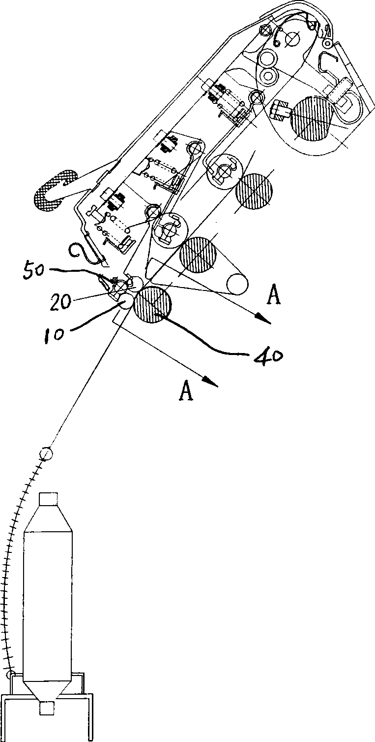
[0028] see image 3 It is the structural representation and the structure diagram of the top spinning machine of the present invention Figure 4 for image 3 As shown in the schematic diagram of the A-A sectional structure of , a self-adjusting parallel front rubber roller device, the front rubber roller 10 is held by the gripper 50 and arranged above the front bottom roller 40 of the ring spinning machine, the front rubber roller 10 and the front bottom roller The roller 40 forms the nip for drafting the roving, wherein the self-adjusting parallel front rubber roller device consists of two groups of front rubber rollers 10, 20 that are axially parallel to each other and are jointly arranged on a pressure seat 30, and the two groups of front rubber rollers The surfaces of the rubber rollers 11, 12 are attached to the surface of the front bottom roller 40 and rotate around the axis respectively, and the gripping claw 50 is held at the pressing seat 30.

[0029] Two arc-shaped...


PUM


Abstract

The invention provides a self-adjusting parallel front rubber roller device, relating to technology improvement for a ring spinning machine. A front rubber roller is held by a grasp claw and is arranged above a lower front roller of the ring spinning machine, and the front rubber roller together with the lower front roller forms a jaw for drafting coarse yarns, wherein, the self-adjusting parallel front rubber roller device is constructed by arranging two groups of front rubber rollers which are parallel with each other at a pressurizing seat, both the surfaces of the two groups of the front rubber rollers cling to the surface of the lower front roller and respectively rotate around the shaft, and the the pressurizing seat is held by the grasp claw. In the invention, traditional single front rubber roller is replaced by two groups of front rubber rollers with a self-adjusting parallel function, the surfaces of the front rubber rollers keep clinging to the surface of the lower front roller throughout the process to apply uniform grasp to the yarn strips, and the quality of the produced yarns is improved; what is more practical is that the invention can be applied to currently widely and massively used spinning machines, new and old, and costs little transformation fee, the operation is simple and convenient, and the device can produce high quality yarns.

Description

technical field [0001] The invention relates to the technical transformation of the front rubber rollers of traditional ring spinning machines, including domestic models and imported models, especially a self-adjusting parallel front rubber roller device, so that there is self-adjustment between the front rubber roller and the front bottom roller. Parallel functions, the axes of the two are always kept parallel. Background technique [0002] figure 1 It is a structural schematic diagram of a traditional ring spinning machine. The main structure includes three pairs of front, middle and rear rubber rollers and rollers installed on the cradle. The rubber rollers are held by grippers and set above the corresponding rollers. Among them, the exit of the front rubber roller 1' and the front bottom roller 2' is the yarn twisting triangle 3', and the part of the yarn from the nip of the front bottom roller to the yarn guide groove 5' is the spinning section 4'. The portion from th...

Claims


Application Information

Patent Timeline
Patent Type & Authority Applications(China)
IPC IPC(8): D01H5/70D01H5/44
Inventor 王林尧张德良戴自怡金凤珊周文华
Owner SHANGHAI TEXTILE GRP DETECTION STANDARD CO LTD
Learn More