

Multi-shaft numerical control machining knife rail generating method for product triangle grid model
A triangular mesh and model technology, applied in simulators, program control, computer control, etc., can solve problems such as tool path generation in multi-axis CNC machining
Inactive Publication Date: 2009-08-19
SHANDONG UNIV OF TECH
View PDF0 Cites 17 Cited by
- Summary
- Abstract
- Description
- Claims
- Application Information
AI Technical Summary
Problems solved by technology
To sum up, the existing triangular mesh model NC machining toolpath generation method cannot be directly used for multi-axis NC machining toolpath generation. Therefore, the rapid generation of multi-axis NC machining toolpaths based on the triangular mesh model has become a challenge for those skilled in the art. technical issues to be resolved
Method used
View moreImage
Smart ImageViewing Examples

Examples
Embodiment
Login to View More PUM
 Abstract
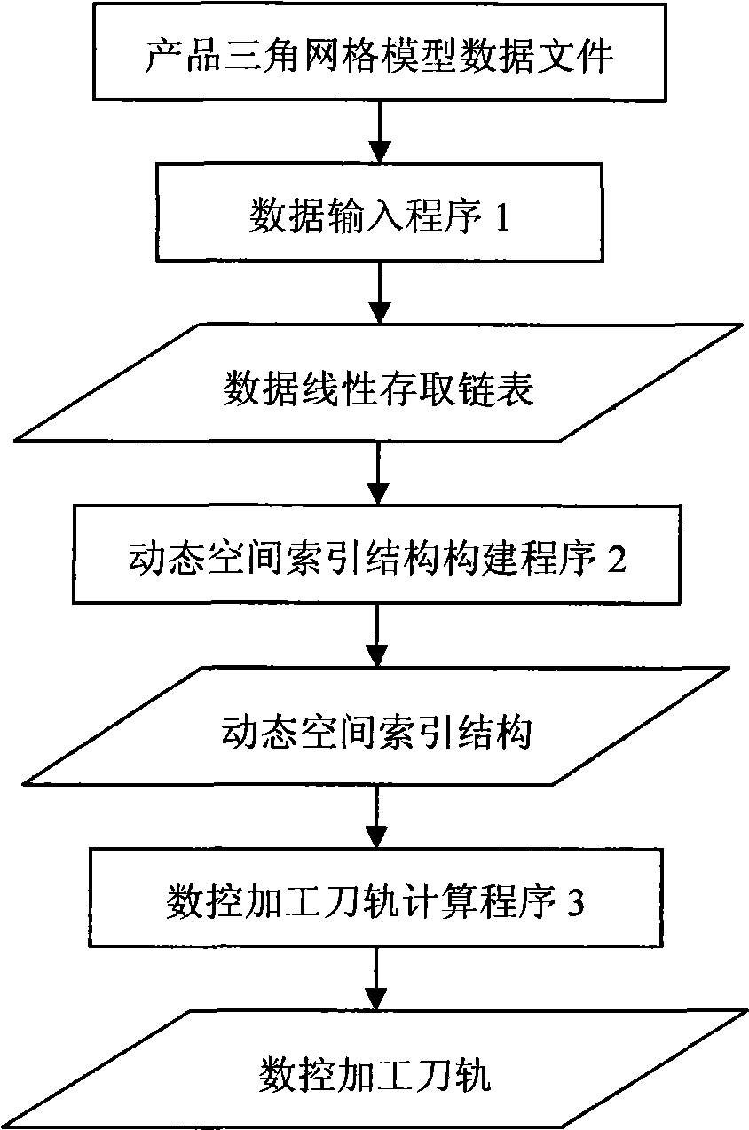
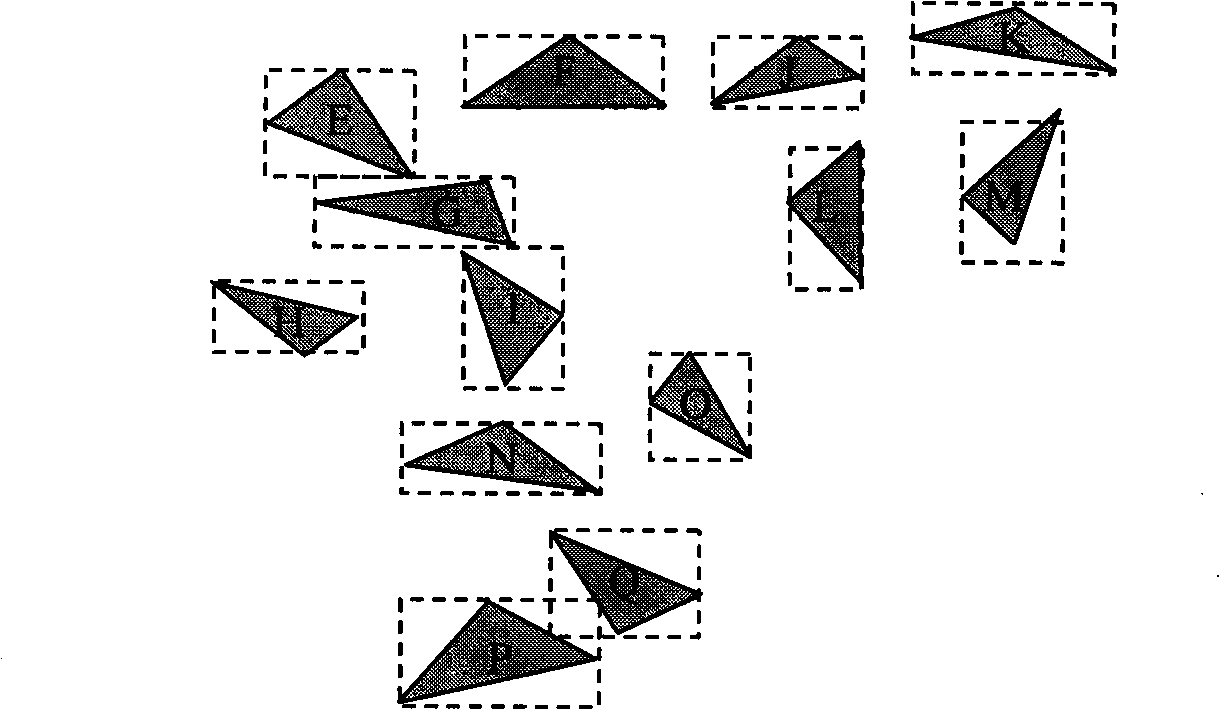
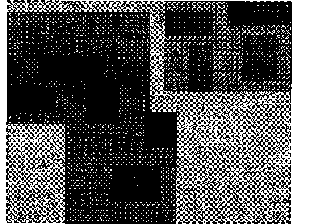
The invention provides a multi-axis numerical control machining tool path generation method for the triangular mesh model of a product, and is characterized in that: a R*S-tree dynamic space index structure organization triangle patch topological neighbor relationship is adopted; based on the structure, the intersection is carried out to the tool-path cross-section and the triangular mesh model for obtaining a cross-section data point; according to an area averaging method, the vector of the corresponding cross-section data point is calculated; the instantaneous processing area corresponding to each cross-section data point is inquired; according to the tangent relationship between the tool and the surface, edge, and vertex of each triangle in the instantaneous processing area, a tool path calculation method of surface tangency, edge tangebcy or vertex tangency is adopted for obtaining corresponding cutting points; a minimum tree generation method is adopted for arranging the cutting points in sequence; and a multi-axis numerical control machining tool path is generated. The method is suitable for the generation of the multi-axis numerical control machining tool path of various complex triangular mesh models, and has high algorithm running efficiency.
Description
technical field The invention provides a multi-axis numerical control machining tool path generation method for a triangular mesh model of a product, belonging to the technical field of computer-aided manufacturing. Background technique In product reverse engineering, equipment such as laser scanners is usually used to obtain scattered point cloud data on the surface of the product solid model, and the data is triangulated to generate a triangular mesh model, which approximates the original solid model. The direct generation of CNC machining tool paths based on the triangular mesh model can avoid the reconstruction process of the product CAD model and the cumulative error of model reconstruction, thereby effectively improving the product development efficiency and machining accuracy based on reverse engineering. Searching the prior art literature found that in the academic paper "Calculation method of tool position trajectory based on triangular mesh surface model" publishe...
Claims
Login to View More Application Information
Patent Timeline
 IPC IPC(8): G05B19/4099
Inventor孙殿柱崔传辉朱昌志刘健
OwnerSHANDONG UNIV OF TECH