
Device and method for detecting initial position angle of double fed electric machine rotor

A technology of rotor initial position and doubly-fed motor, which is applied in the field of detection, can solve the problems of difficult realization, large rotor moment of inertia, high motor requirements, etc., and achieves the effects of convenient use, easy operation, simple and reliable structure, and wide application range

Inactive Publication Date: 2009-08-19
CHINA UNIV OF MINING & TECH
View PDF0 Cites 5 Cited by
  • Summary
  • Abstract
  • Description
  • Claims
  • Application Information

AI Technical Summary

Problems solved by technology

This test method is more convenient for the small-capacity doubly-fed speed control system to detect the initial position of the rotor; but for the large-capacity fan and pump speed control system, due to the large capacity of the motor and the large moment of inertia of the rotor, it is very difficult to realize. Moreover, the implementation of the test method requires instruments and professionals. After the encoder is replaced, the test is still required, and the detection accuracy is also difficult to control; the versatility is poor, and it is only suitable for specific types of motors. It has high requirements for the motor and requires special instruments. Accuracy is difficult to control

Method used


Image

  • Device and method for detecting initial position angle of double fed electric machine rotor
  • Device and method for detecting initial position angle of double fed electric machine rotor
  • Device and method for detecting initial position angle of double fed electric machine rotor

Examples


Embodiment Construction

[0012] The present invention will be further described below in conjunction with the embodiment in the accompanying drawings:

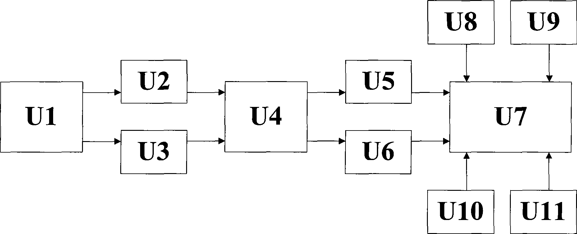
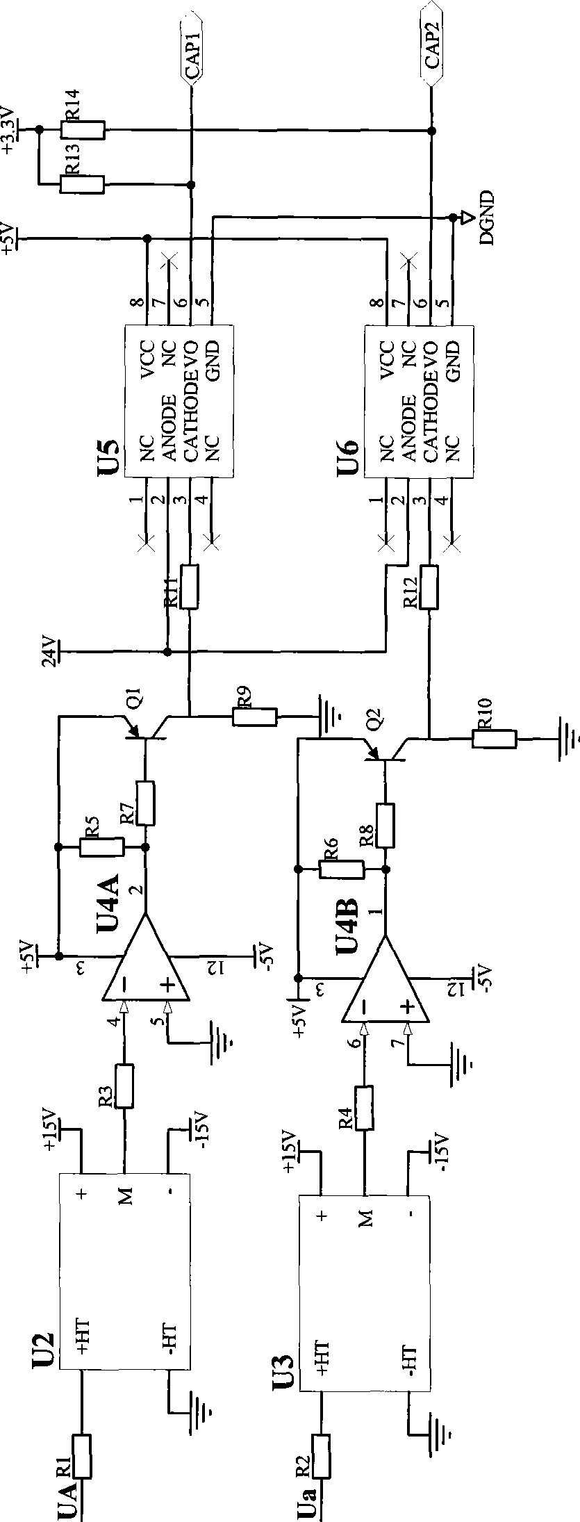
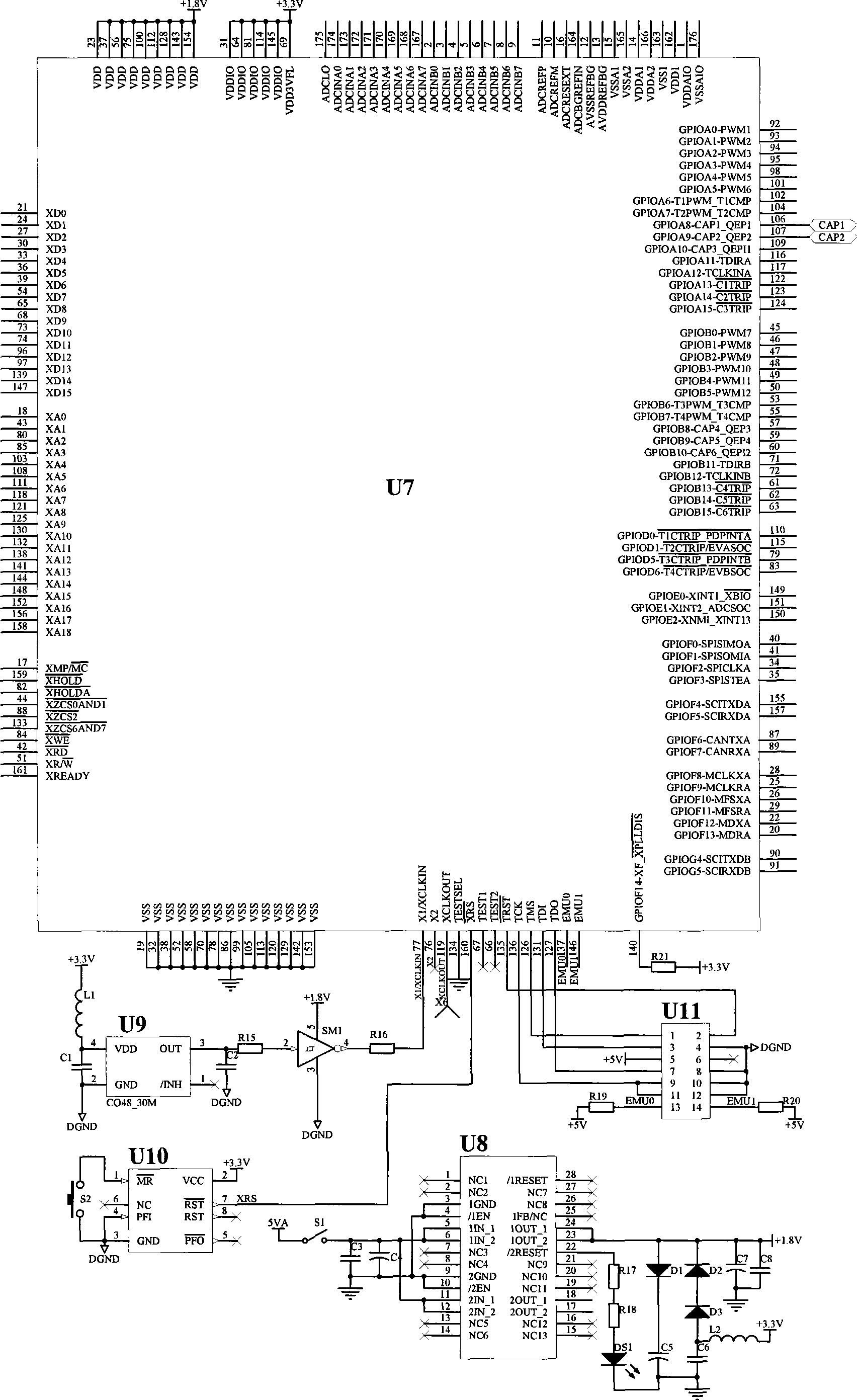
[0013] figure 1 Shown: The circuit is mainly composed of voltage detection circuit U2, U3, zero-crossing comparison circuit U4, photoelectric isolation circuit U5, U6, DSP processor U7, power supply circuit U8, clock circuit U9, watchdog circuit U10, JTAG interface circuit U11 . The voltage detection circuits U2 and U3 are respectively connected to the stator and rotor of the doubly-fed motor U1, and are respectively used to detect the induced electromotive force output by the stator and rotor sides of the doubly-fed motor U1, and convert the induced electromotive force into a weak current signal; the voltage detection circuit U2 and U3 are respectively connected to the zero-crossing comparison circuit U4, which converts the stator and rotor induced electromotive force detected by the voltage detection circuits U2 and U3 into square wave signals; the...


PUM


Abstract

The invention relates to an initial position angle detecting device of a double-feed motor rotor and a method thereof. The device includes voltage detecting circuits that are respectively connected with a stator and a rotor of the doubly-fed machine. The voltage detecting circuits are respectively used for detecting the induced electromotive force which is output by the stator side and the rotor side of the double-feed motor, and converting the induced electromotive force into weak electrical signals. The voltage detecting circuits are respectively connected with zero crossing comparison circuits which convert the detected induced electromotive force output by the stator and the rotor of the voltage detecting circuits into square wave signals; the output ends of the zero crossing comparison circuits are respectively connected with two groups of photoelectric isolation circuits which deliver the square wave signals output by the zero crossing comparison circuits into a main processor circuit that processes data. The device is not only applicable to double-feed motors with small capacity but also to large-capacity fans and double-feed speed adjusting systems of pumps and the like. The structure of the device is simple and reliable, regardless of the connection way of the stator winding and the rotor winding. The device is characterized by the convenient use and easy operation, high test precision and wide application scope.

Description

technical field [0001] The invention relates to the technical field of detection quantities, in particular to a device and method for detecting an initial position angle of a doubly-fed motor rotor. Background technique [0002] Accurate and reliable rotor position signal is a necessary condition for the normal operation of high-performance double-fed speed control system. The existing rotor initial position detection scheme mainly draws on the initial positioning scheme of synchronous motors. DC current is simultaneously passed into the three-phase windings of the stator and rotor of the doubly-fed motor, and the rotor rotates under the action of electromagnetic torque, which is recorded by a digital signal processor. The value of the photoelectric encoder after the rotor is stationary, and calculate the initial position angle. Although this method is relatively simple, because it does not consider the connection method of the stator and rotor windings, if it is used direc...

Claims


Application Information

Patent Timeline
IPC IPC(8): H02P23/00H02P6/18
Inventor 伍小杰于月森戴鹏石婷婷钱振华左东升王贵峰周娟夏帅符晓彭利明
Owner CHINA UNIV OF MINING & TECH
Learn More