
Thermoelectric facility comprising a thermoelectric generator and means for limiting the temperature on the generator

A technology of thermoelectric devices and generators, applied to engine components, machines/engines, thermoelectric devices that only use the Peltier or Seebeck effect, etc., can solve problems such as limiting the temperature of generators, and achieve the effect of buffering temperature fluctuations

Inactive Publication Date: 2009-08-19
SIEMENS AG
View PDF9 Cites 3 Cited by
  • Summary
  • Abstract
  • Description
  • Claims
  • Application Information

AI Technical Summary

Problems solved by technology

The thermal contact surface with the thermoelectric generator, which can change with the temperature conditions, especially when using meltable solders, leads to limiting the temperature of the generator

Method used


Image

  • Thermoelectric facility comprising a thermoelectric generator and means for limiting the temperature on the generator
  • Thermoelectric facility comprising a thermoelectric generator and means for limiting the temperature on the generator
  • Thermoelectric facility comprising a thermoelectric generator and means for limiting the temperature on the generator

Examples


Embodiment Construction

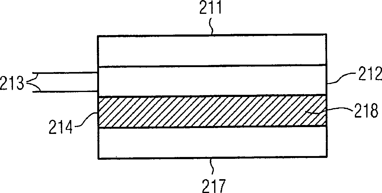
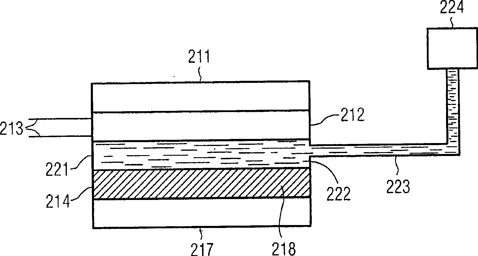
[0040] figure 1 The schematic representation shows the structure of the thermoelectric device according to the preferred embodiment. Its thermoelectric generator 212 is thermally connected to the cold source 211 on the first side over a large area. The hot side of the thermoelectric generator 212 is thermally connected to the cavity 214 filled with the meltable first working medium 218 in a large area. The first cavity 214 is thermally connected to the heat source 217 over a large area. The thermal connection between the above-mentioned elements can preferably be realized by a mechanical connection of the same large area.

[0041] The heat source 217 and the cold source 211 cause a temperature gradient to be formed on the thermoelectric generator 212. The voltage can be intercepted on the electrical connector 213 of the thermoelectric generator 212.

[0042] To illustrate, press figure 1 The operating mode of the thermoelectric device of the preferred embodiment shown can be ba...


PUM


Abstract

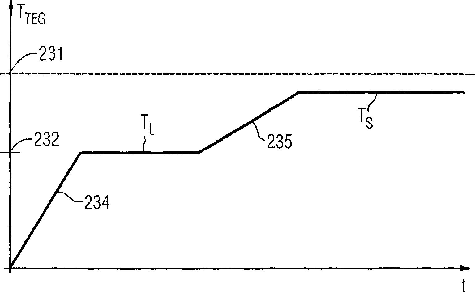
The thermoelectric facility contains a thermoelectric generator (212) which is thermally connected on a first side to a heat source (217) and on a second side to a heat sink (211). The thermoelectric facility also has means for limiting the temperature on the thermoelectric generator (212). Said means comprise a first compartment (214), filled with a first working medium (218) that can melt, which compartment is connected across a large surface thereof to the heat source (217) or to a second compartment (221) that is filled with an evaporable second working medium (222). The second compartment (221) is connected to the thermoelectric generator (212) on its side facing away from the first compartment (214). The working media (218, 222) have a predetermined melting point (TL) or boiling point (TS) in order to prevent permanent damages to the thermoelectric generator (212).; The thermoelectric facility is especially useful for motor vehicles that are operated by an internal combustion engine.

Description

Technical field [0001] The present invention relates to a thermoelectric device, which includes [0002] a) Thermoelectric generator, heat source and cold source, wherein the thermoelectric generator is thermally connected to the heat source on the first side and the cold source on the second side, and [0003] b) The temperature limiting device of the thermoelectric generator, which includes a first cavity with flat opposite faces, and the size of the cavity is adapted to the size of the thermoelectric generator, [0004] The first cavity is at least basically filled with a meltable first working fluid, which has a melting point T lower than the critical temperature L , Exceeding the critical temperature will permanently damage the thermoelectric generator. Background technique [0005] This kind of thermoelectric device is known from EP1522685A1. [0006] The direct conversion of thermal energy into electrical energy can be achieved with the help of so-called thermoelectric gen...

Claims


Application Information

Patent Timeline
Patent Type & Authority Applications(China)
IPC IPC(8): H01L35/30F02G5/02H10N10/13
CPCH01L35/30Y02E20/14H10N10/13
Inventor 西蒙·休廷格
Owner SIEMENS AG
Learn More