Blade of vertical wind driven generator

A technology for wind turbines and blades, applied in the field of blades, which can solve the problems that the size of the windward surface of the blades cannot be controlled, and it is difficult to prevent vertical wind turbines from failing or even being damaged, and achieve the effects of light weight, low resistance, and low viscosity

Active Publication Date: 2009-08-26
GUANGZHOU YATU NEW ENERGY TECH
View PDF0 Cites 4 Cited by
  • Summary
  • Abstract
  • Description
  • Claims
  • Application Information

AI Technical Summary

Problems solved by technology

In wind turbines, the high or low utilization rate of wind energy mainly depends on the structure and structure of the blades; at present, the blades of vertical wind turbines have various shapes, such as fan-shaped structure, sail-shaped structure, φ-shaped structure, etc. In these structures Among th...

Method used


Image

  • Blade of vertical wind driven generator
  • Blade of vertical wind driven generator
  • Blade of vertical wind driven generator

Examples


no. 1 approach

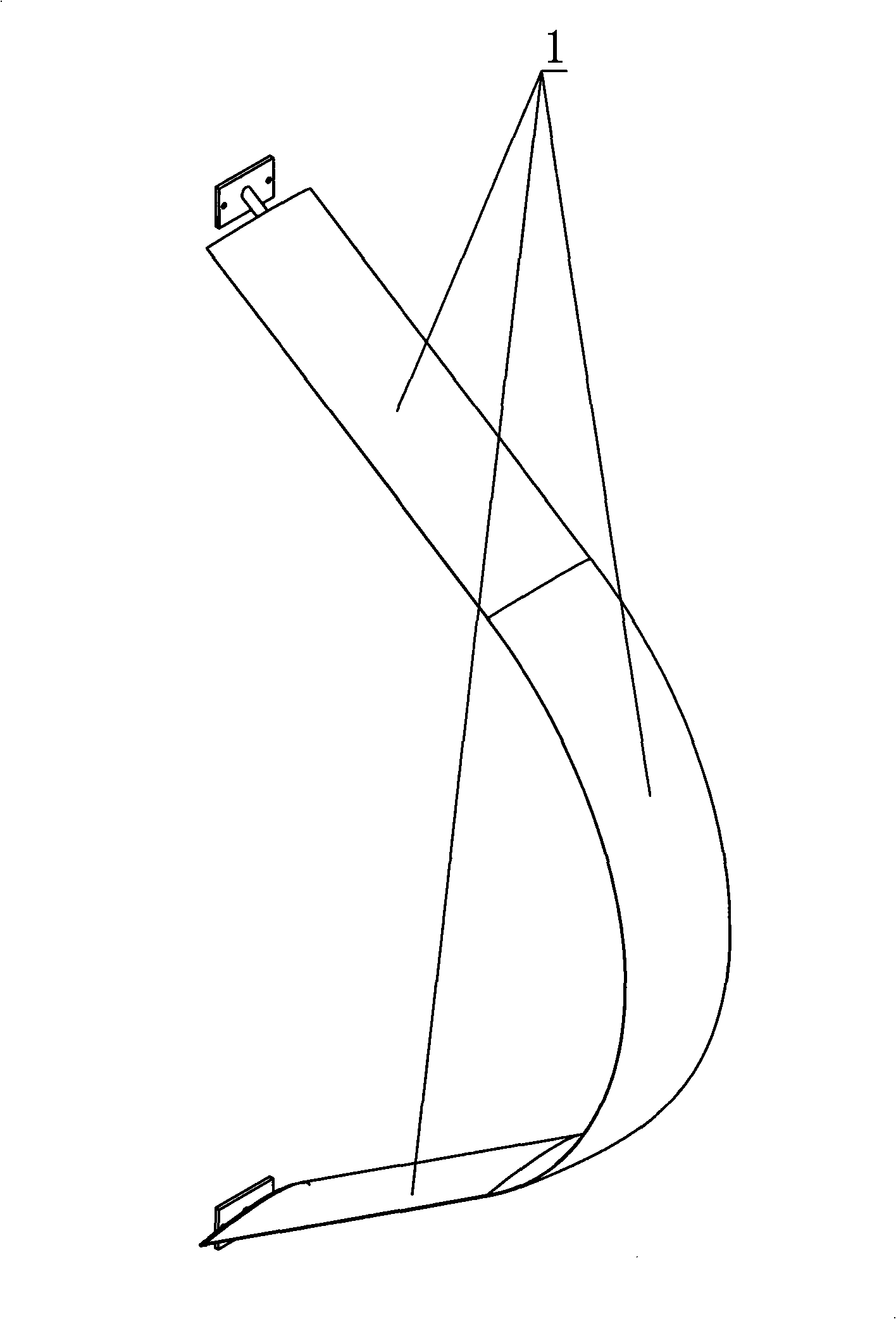
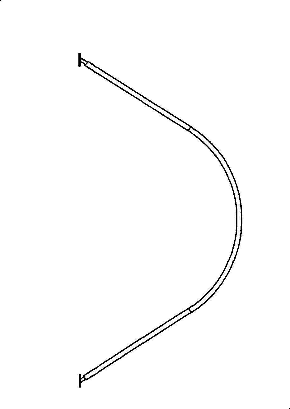
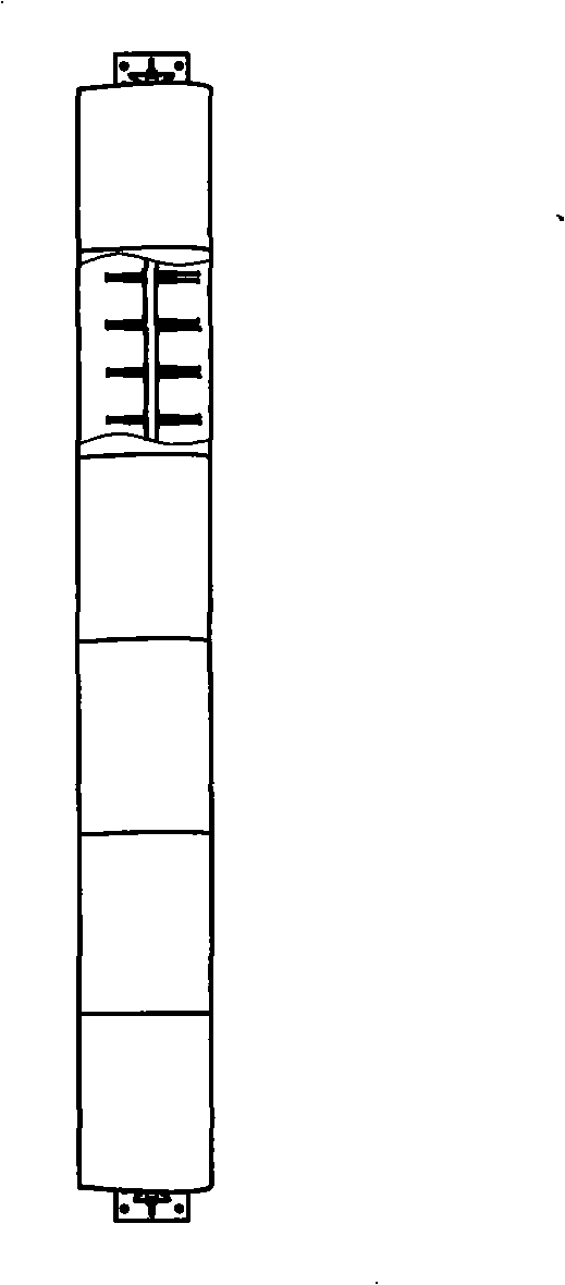
[0030] Such as Figure 1 to Figure 4 As shown in the vertical wind power generator blade, the blade is composed of three blade units 1; as Figure 4 , the cross-section of the blade unit 1 is olive-shaped with a large middle and small ends, and one of the two small ends is a round end, and the other end is a tip. The blade unit 1 adopts this cross-sectional structure, which has a high utilization rate of wind energy. The blade unit 1 includes a skeleton 101, a blade body 102, a first blade tip 103 and a second blade tip 104; the blade body 102 is installed on the skeleton 103, and the skeleton 103 is inside the blade body 102; The tip 103 is arranged at one end of the airfoil 102 along the radial direction of the blade unit 1, the tail portion 1031 of the first blade tip 103 is the round end, and the head 1032 of the first blade tip 103 extends into the airfoil 102 The second blade tip 104 is arranged on the end of the blade body 102 opposite to the first blade tip 103 along ...

no. 2 approach

[0033] Such as figure 1 , figure 2 , image 3 and Figure 8 As shown in the vertical wind power generator blade, the blade is composed of three blade units 1; as Figure 8 , the cross-section of the blade unit 1 is olive-shaped with a large middle and small ends, and one of the two small ends is a round end, and the other end is a tip. The blade unit 1 adopts this cross-sectional structure, which has a high utilization rate of wind energy. The blade unit 1 includes a skeleton 101, a blade body 102, a first blade tip 103 and a second blade tip 104; the blade body 102 is installed on the skeleton 103, and the skeleton 103 is inside the blade body 102; The tip 103 is arranged at one end of the airfoil 102 along the radial direction of the blade unit 1, the tail portion 1031 of the first blade tip 103 is the round end, and the head 1032 of the first blade tip 103 extends into the airfoil 102 The second blade tip 104 is arranged on the end of the blade body 102 opposite to the...

no. 3 approach

[0036] Such as figure 1 , figure 2 , image 3 and Figure 12 As shown in the vertical wind power generator blade, the blade is composed of three blade units 1; as Figure 12 , the cross-section of the blade unit 1 is olive-shaped with a large middle and small ends, and one of the two small ends is a round end, and the other end is a tip. The blade unit 1 adopts this cross-sectional structure, which has a high utilization rate of wind energy. The blade unit 1 includes a skeleton 101, a blade body 102, a first blade tip 103 and a second blade tip 104; the blade body 102 is installed on the skeleton 103, and the skeleton 103 is inside the blade body 102; The tip 103 is arranged at one end of the airfoil 102 along the radial direction of the blade unit 1, the tail portion 1031 of the first blade tip 103 is the round end, and the head 1032 of the first blade tip 103 extends into the airfoil 102 The second blade tip 104 is arranged on the end of the blade body 102 opposite to t...


PUM


Abstract

The invention provides blades of a vertical wind driven generator. The vertical wind driven generator comprises more than one blade units. The blade units comprise a frame and a blade body, the blade body is arranged on the frame, one end of the blade body is provided with a first blade tip and the other end of the blade body is provided with a second blade tip in the radial direction of the blade units, a first movement device driving the first blade tip to move along the radial direction of the blade units is arranged between the frame and the first blade tip, and a second movement device driving the second blade tip to move along the radial direction of the blade units is arranged between the frame and the second blade tip. The blade structure can help adjust size of windward side of the blades so as to automatically adjust power of the wind driven generator and prevent failure of the wind driven generator resulting from overhigh wind speed and improve utilization of wind energy.

Description

technical field [0001] The invention relates to a blade of a vertical wind power generator, especially a retractable blade used on a phi-shaped wind rotor. Background technique [0002] Now, the resources of non-renewable energy are less and less, and even some energy has been consumed. Therefore, the reduction of energy will become an obstacle for people's life and work. In order to solve these problems, people have begun to develop some new energy sources, such as wave energy, combustible ice, coal bed methane, and microorganisms. These energy sources will become new energy sources widely used by humans. New energy sources such as wind energy are used in many regions and equipment. It has already begun to be used, especially on wind turbines, and its technology has slowly begun to mature. In wind turbines, the high or low utilization rate of wind energy mainly depends on the structure and structure of the blades; at present, the blades of vertical wind turbines have vario...

Claims


Application Information

Patent Timeline
IPC IPC(8): F03D3/06
CPCY02E10/74Y02E10/728
Inventor 邓允河
Owner GUANGZHOU YATU NEW ENERGY TECH
Why Eureka
Try Eureka