Hydrogen chloride compressor

A technology of hydrogen chloride and compressors, which is applied in the direction of mechanical equipment, machines/engines, liquid fuel engines, etc., can solve the problems of small conveying capacity, high cost, pulsation of gas conveying pressure, etc., and achieve simple structure, long service life and conveying pressure stable effect

Inactive Publication Date: 2009-08-26
HANGZHOU ZHENXING IND PUMP MFG
View PDF0 Cites 12 Cited by
  • Summary
  • Abstract
  • Description
  • Claims
  • Application Information

AI Technical Summary

Problems solved by technology

[0007] The technical problem to be solved in the present invention is to provide a hydrogen chloride compressor, which mainly solves the problems in the prior art that the efficiency is very low if a liquid ring compressor is used, and if the pressure is further increased, the efficiency is even lower, such as using a diaphragm The traditional compressor has relatively small delivery capacity, large gas delivery pressure pulsation, and high cost technical problems.

Method used


Image

  • Hydrogen chloride compressor
  • Hydrogen chloride compressor
  • Hydrogen chloride compressor

Examples


Embodiment 1

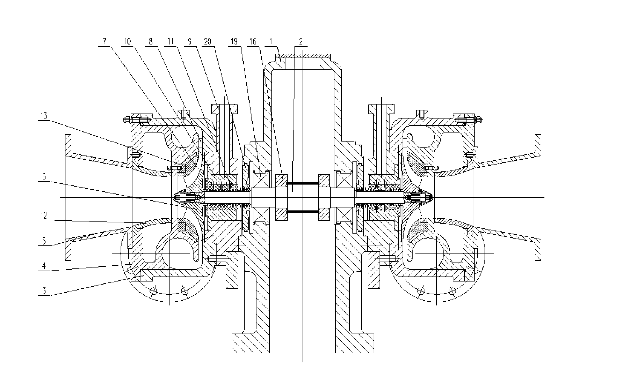
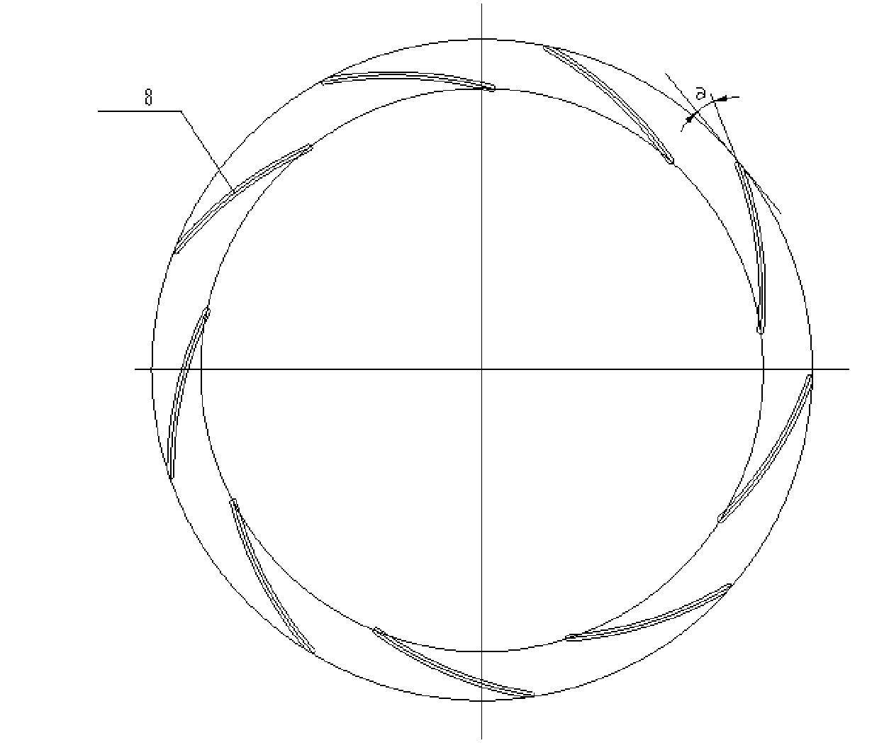
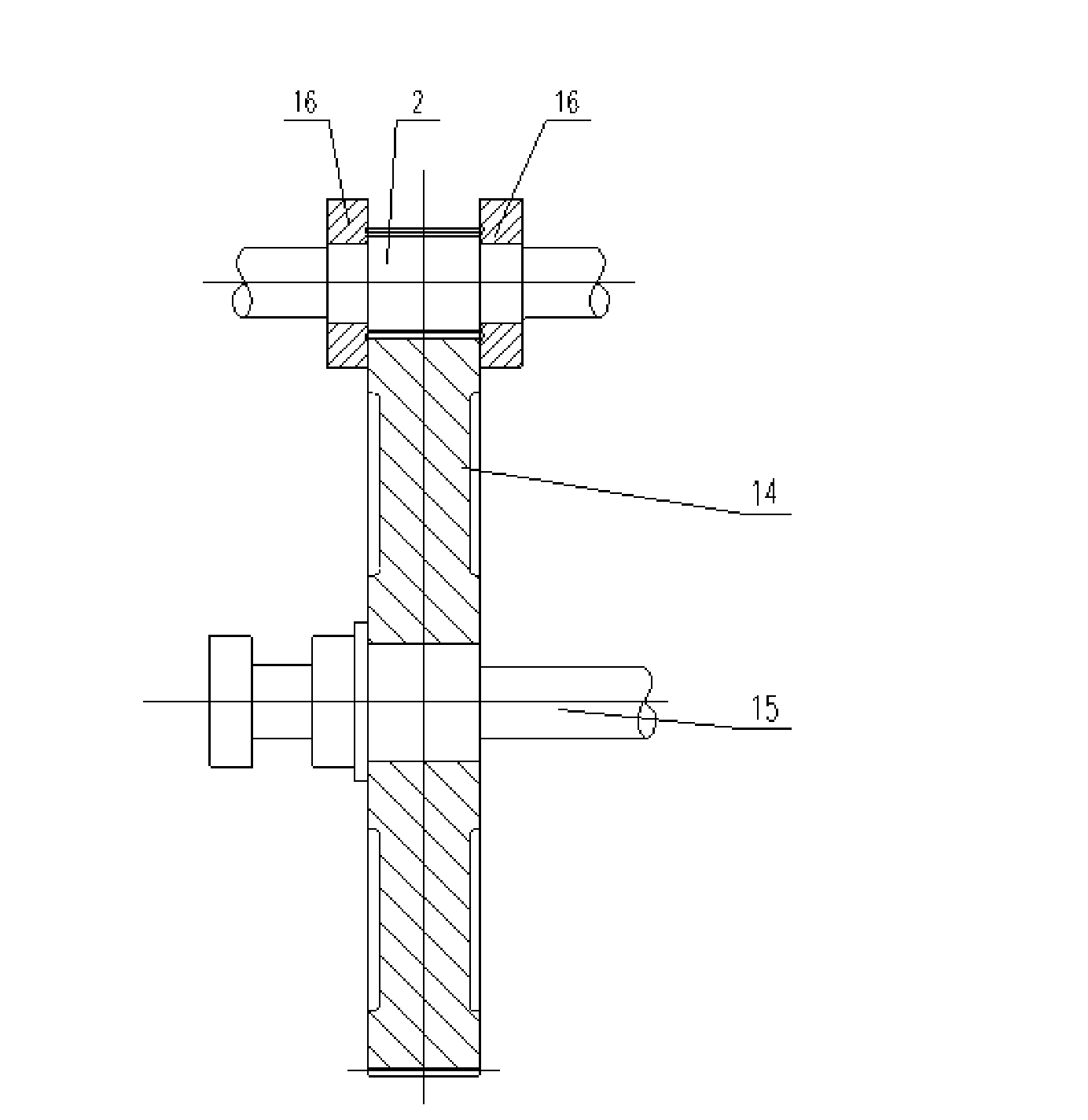
[0027] Embodiment 1: the hydrogen chloride compressor of this example, as figure 1 , image 3 , there is a gear speed-up box 1, the gear shaft 2 is connected through the gear speed-up box, the middle part of the gear shaft 2 is meshed with a large gear 14, the large gear is connected with a low-speed shaft 15, and the meshing part of the gear shaft 2 and the large gear 14 A thrust plate 16 is respectively connected to both sides. The two ends of the gear shaft 2 stretch out outside the gear speed-up box, and a tiltable pad sliding bearing 19 is arranged between the gear speed-up box and the gear shaft. Both sides of the gear speed increasing box 1 are respectively connected with a compression part, and the compression part includes an inlet pipe 5, a volute inner body 4, a stationary wheel cover 13, a volute 3 and an air seal assembly. Two inlet pipes 5 are connected to the opening of the volute inner body 4, and the inlet pipes are all arranged horizontally. The inside of ...

Embodiment 2

[0029] Embodiment 2: the hydrogen chloride compressor of this example, as Figure 4, there is a gear speed-up box 1, the gear shaft 2 is threaded through the gear speed-up box, the middle part of the gear shaft 2 is meshed with a bridge gear 17, and the bridge gear 17 is meshed with a large gear 14 through a medium-speed shaft 18, and the large gear wears A low-speed shaft 15 is connected, and a thrust plate 16 is respectively connected to both sides of the gear shaft 2 meshing with the bridge gear 17 . The two ends of the gear shaft 2 stretch out outside the gear speed-up box, and a tiltable pad sliding bearing 19 is arranged between the gear speed-up box and the gear shaft. Both sides of the gear speed increasing box 1 are respectively connected with a compression part, and the compression part includes an inlet pipe 5, a volute inner body 4, a stationary wheel cover 13, a volute 3 and an air seal assembly. The inlet pipe 5 is connected to the opening of the volute inner bo...


PUM


Abstract

The invention relates to a centrifugal type compressor, especially to a hydrogen chloride compressor, and mainly solves technical problems that in prior art if liquid-ring compressor is employed, efficiency is low, if pressure is further increased, efficiency is lower, if diaphragm type compressor is employed, transportation capability is relatively smaller, gas transportation pressure pulsation is larger and cost is higher. The hydrogen chloride compressor includes a gear speedingup box, and a gear shaft which perforates and is connected with the gear speedingup box, and is characterized in that the gear shaft is connected with a driving device, the gear speedingup box is connected with a compression component which includes a spiral case, a spiral case inner body is arranged in the spiral case, an opening is arranged at the spiral case inner body and is connected with a inlet pipe, a impeller opposite to the inlet pipe is arranged in the spiral case inner body and is connected with a gear shaft, a medium outlet flow passage is arranged between the spiral case inner body and the spiral case, a diffuser is arranged at the medium outlet flow passage, and a gas sealing component is arranged between the impeller and the gear speedingup box.

Description

technical field [0001] The invention relates to a centrifugal compressor, in particular to an improvement on the structures of hydrogen chloride compressors and the like. Background technique [0002] Hydrogen chloride gas (HCl) is used to prepare SiHCl 3 raw material gas, while SiHCl 3 It is an important intermediate for the manufacture of silane coupling agents and other silicone products, and it is also the main raw material for the manufacture of high-purity polysilicon. Polysilicon production enterprises at home and abroad generally adopt the closed-loop trichlorosilane hydrogen reduction process. This method is to synthesize hydrogen chloride (or purchased hydrogen chloride) with chlorine and hydrogen, and synthesize trichlorohydrin and industrial silicon powder at a certain temperature. Hydrogen silicon, and then separate and rectify trichlorosilane to purify, and the purified trichlorosilane is subjected to CVD reaction in a hydrogen reduction furnace to produce hi...

Claims


Application Information

Patent Timeline
Patent Type & Authority Applications(China)
IPC IPC(8): F04D17/10F04D29/44F04D29/08F04D25/16F04D29/053F04D29/056
Inventor 温建新李月仙倪建军陈杰蔡利平
Owner HANGZHOU ZHENXING IND PUMP MFG
Why Eureka
Try Eureka