A remote pump optic fiber amplifying module

A technology of optical fiber amplification and remote pumping, which is applied in optics, light guides, lasers, etc., can solve problems such as difficult operation, inability to transmit optical signals, and inability to realize optical signal transmission, and achieve the effects of increasing scanning area, expanding functions, and optimizing methods

Inactive Publication Date: 2009-08-26
NO 34 RES INST OF CHINA ELECTRONICS TECH GRP
View PDF0 Cites 12 Cited by
  • Summary
  • Abstract
  • Description
  • Claims
  • Application Information

AI Technical Summary

Problems solved by technology

The existing remote-pumped optical fiber amplifier module is equipped with an isolator, so that only one-way transmission of optical signals can be realized, and optical signal transmission in the opposite direction cannot be realized, such as figure 1 shown
When the transmission fiber of the remote-pumped optical fiber amplifier module with this structure is installed fails, and it is necessary to use an optical time domain reflectometer (OTDR) for fault location, if the OTDR optical signal is transmitted from the forward direction to the remote pumped optical fiber amplifier module, due to the The internal isolator only supports one-way transmission, so the OTDR optical signal cannot be transmitted back, and the OTDR cannot measure the transmission optical fiber after the remote pump optical fiber amplifier module
If the optical signal of the OTDR is transmitted from the reverse direction to the remote pumping optical fiber amplifier module, because the isolator inside the module does not support the transmission of the reverse optical signal, the optical signal of the OTDR will not pass through the remote pumping optical fiber amplifier module
It can be seen that using OTDR to locate the fiber optic fault on the fiber optic line installed with the existing remote pump fiber amplifier module can only scan and locate the fault section by section between two sites, but cannot realize the fault location of the entire section of the fiber optic line
This optical fiber fault location method seems to simply increase the number of measurements, but it is quite difficult to actually operate in areas where remote pumped optical fiber amplifier modules are used (that is, areas where relay sites cannot be established)

Method used


Image

  • A remote pump optic fiber amplifying module
  • A remote pump optic fiber amplifying module
  • A remote pump optic fiber amplifying module

Examples


Embodiment Construction

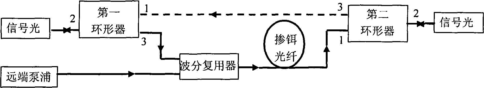
[0011] A remote pump optical fiber amplification module of the present invention such as figure 2 As shown, its interior is composed of two three-port circulators, a wavelength division multiplexer and at least one section of erbium-doped optical fiber. Port 1 of the first circulator of the above two circulators is connected to port 3 of the second circulator, port 3 of the first circulator is connected to one of the input terminals of the wavelength division multiplexer, and the output port of the wavelength division multiplexer It is connected to port 1 of the second circulator, the optical signal is input from port 2 of the first circulator, and output from port 2 of the second circulator. The erbium-doped optical fiber can be connected in series between the input end of the wavelength division multiplexer and the first circulator, or between the output end of the wavelength division multiplexer and the second circulator, or at the same time. terminal and the first circul...


PUM

PropertyMeasurementUnit
isolationaaaaaaaaaa

Abstract

The invention discloses a remote pump optic fiber amplifying module comprising a wavelength division multiplexer, at least a section of erbium-doped fiber and two circulators each having three ports. The port 1 of the first circulator is connected with the port 3 of the second circulator, wherein the port 3 of the first circulator is connected with one input end of the wavelength division multiplexer; the output input end of the wavelength division multiplexer is connected with the port 1 of the second circulator, thus optical signal is input from the port 2 of the first circulator and output from the port 2 of the second circulator. The erbium-doped fiber is serially connected between the input end of the wavelength division multiplexer and the first circulator, and / or between the output end of the wavelength division multiplexer and the second circulator; while the other input end of the wavelength division multiplexer is connected with the output end of the remote pump. The invention can provides passage for reversal feedback optical signal, ensure the optical signal of OTDR to be transparently transmitted through the remote pump optic fiber amplifying module, accordingly, the function of the remote pump optic fiber amplifying module can be expanded.

Description

technical field [0001] The invention belongs to an optical fiber amplification module in the field of optical fiber communication, in particular to a remote pump optical fiber amplification module. Background technique [0002] The remote pump optical fiber amplifier module is mainly used in some special areas where relay sites cannot be established to extend the transmission distance of the system. The existing remote-pumped optical fiber amplifier module is equipped with an isolator, so that only one-way transmission of optical signals can be realized, and optical signal transmission in the opposite direction cannot be realized, such as figure 1 shown. When the transmission fiber of the remote-pumped optical fiber amplifier module with this structure is installed fails, and it is necessary to use an optical time domain reflectometer (OTDR) for fault location, if the OTDR optical signal is transmitted from the forward direction to the remote pumped optical fiber amplifier ...

Claims


Application Information

Patent Timeline
Patent Type & Authority Applications(China)
IPC IPC(8): H01S3/067H01S3/094G02B6/26G02B6/293G02F1/095
Inventor 伍浩成陈凯吴国锋欧阳竑阳华吴涛赵灏
Owner NO 34 RES INST OF CHINA ELECTRONICS TECH GRP
Why Eureka
Try Eureka