Control method for compensating location torque of permanent-magnet motor by injecting current harmonics

A permanent magnet motor, positioning torque technology, applied in motor generator control, electronic commutation motor control, control system and other directions, can solve the problem of limited reduction in positioning torque, weakening permanent magnet motor positioning torque, and increasing manufacturing costs. , to reduce the positioning torque, increase the system cost, reduce vibration and noise

Inactive Publication Date: 2010-09-01
SOUTHEAST UNIV
View PDF3 Cites 2 Cited by
  • Summary
  • Abstract
  • Description
  • Claims
  • Application Information

AI Technical Summary

Problems solved by technology

In general, it can be classified into two categories: one is to study the methods of weakening the positioning torque of permanent magnet motors starting from the design of the motor body, such as including stator / rotor skewed slots or oblique poles, magnetic pole shape optimization, fractional slot structure, pole Combination optimization of arc coefficients, rotor segmentation, asymmetric placement of permanent magnets, stator / rotor opening auxiliary slots, optimized design of stator slot width, matching of different slot widths, and optimized design of core shape, etc., but due to many limitations in various aspects, Constrained by the structure of different types of motors, the degree of reduction of the positioning torque is limited. In addition, this type of method for the motor body will not only weaken the positioning torque, but also affect the no-load back electromotive force and power output capability of the motor. The manufacturing cost has certain limitations in the actual industrialization process; the second type of method is to compensate the positioning torque of the motor through the control strategy under the condition that the motor body cannot be improved after the motor has been manufactured, thereby improving its output performance

Method used


Image

  • Control method for compensating location torque of permanent-magnet motor by injecting current harmonics
  • Control method for compensating location torque of permanent-magnet motor by injecting current harmonics

Examples


Embodiment Construction

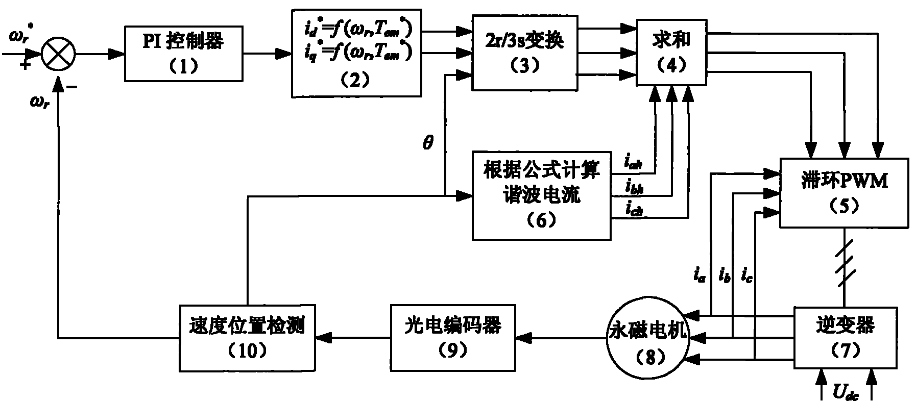
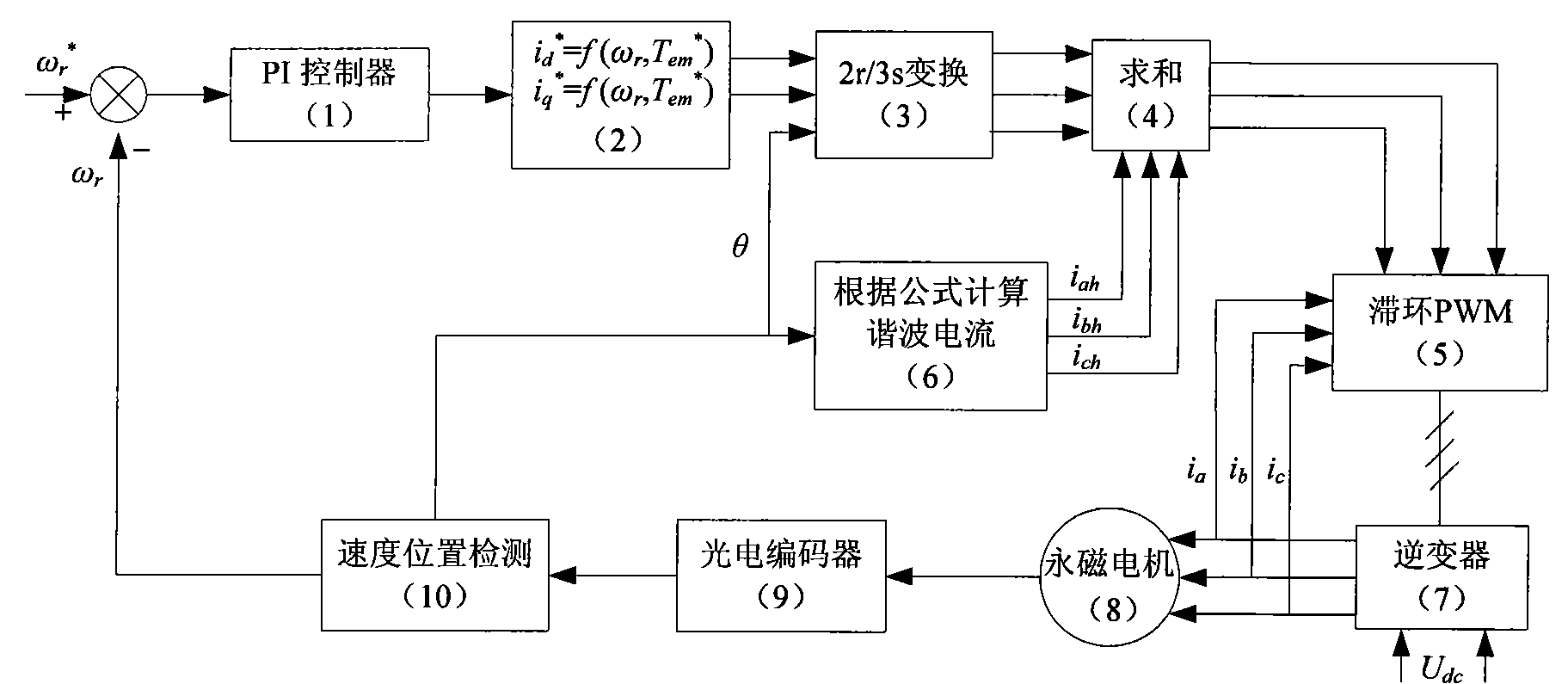
[0014] First, through the finite element simulation results or the measured data of the torque tester, theoretically analyze the positioning torque waveform of the permanent magnet motor, and use the Fourier series to approximate the positioning torque of the FSPM motor and perform harmonic analysis to find out the positioning torque. The fundamental wave and main high-order harmonic components with large amplitude in the torque; secondly, conduct harmonic analysis on the no-load back electromotive force waveform of the permanent magnet motor. Under the premise that the harmonic content can be ignored except the fundamental wave, Write out its mathematical expression; finally, through theoretical analysis and calculation, the injected high-order harmonic current makes it interact with the fundamental permanent magnet magnetic potential, thereby generating the mechanism of additional high-order torque components, making the additional torque and The amplitude of the fundamental ...


PUM


Abstract

The invention discloses a control method for compensating location torque of permanent-magnet motor by injecting current harmonics; in the method, harmonic current is injected to interact with the fundamental wave permanent magnetic potential to generate an additional torque component, so that the additional torque can be equal to the amplitude of the fundamental wave and the ultra-harmonics component in the directional torque and the phase positions thereof are opposite and can be offset, thus achieving the aim of compensating the location torque. In the method, firstly harmonic analysis is carried out on the location torque of the permanent-magnet motor by using finite element simulation result or observed data and adopting the Fourier series approximation approaching method; secondly the aero load counter electromotive force of the permanent-magnet motor is analyzed and the corresponding mathematical expression is written out; and finally the injected harmonic current is worked outaccording to the principle that additional torque and location torque can offset each other.

Description

technical field [0001] The invention relates to a control technology for compensating the positioning torque of a permanent magnet motor by injecting current harmonics, and belongs to the technical field of motor drive and control. Background technique [0002] With the continuous improvement of the cost performance of rare earth permanent magnet material neodymium iron boron (NdFeB), permanent magnet motors are widely used in more and more industrial drive and servo control fields due to their small size, high efficiency, and good dynamic response characteristics. However, in the permanent magnet motor, the permanent magnet interacts with the slotted armature core to generate a positioning torque, which causes vibration and noise during the operation of the motor. The existence of the positioning torque affects the low-speed performance of the motor in the speed control system and in the position control system. high-precision positioning. [0003] Regarding the method of ...

Claims


Application Information

Patent Timeline
Patent Type & Authority Patents(China)
IPC IPC(8): H02P21/00H02P21/14
Inventor 花为程明贾红云杨正专
Owner SOUTHEAST UNIV
Why Eureka
Try Eureka