Energy storage unit

A technology of accumulator and power accumulator, which is applied in the direction of accumulator device, fluid hybrid vehicle, mechanical equipment, etc.

Inactive Publication Date: 2009-08-26
ROBERT BOSCH GMBH
View PDF1 Cites 15 Cited by
  • Summary
  • Abstract
  • Description
  • Claims
  • Application Information

AI Technical Summary

Problems solved by technology

[0004] The disadvantage of said system is that only the accumulator element is connected to the hydrostatic circuit used to drive the vehicle for the accumulation and recovery of energy

Method used


Image

  • Energy storage unit

Examples


Embodiment Construction

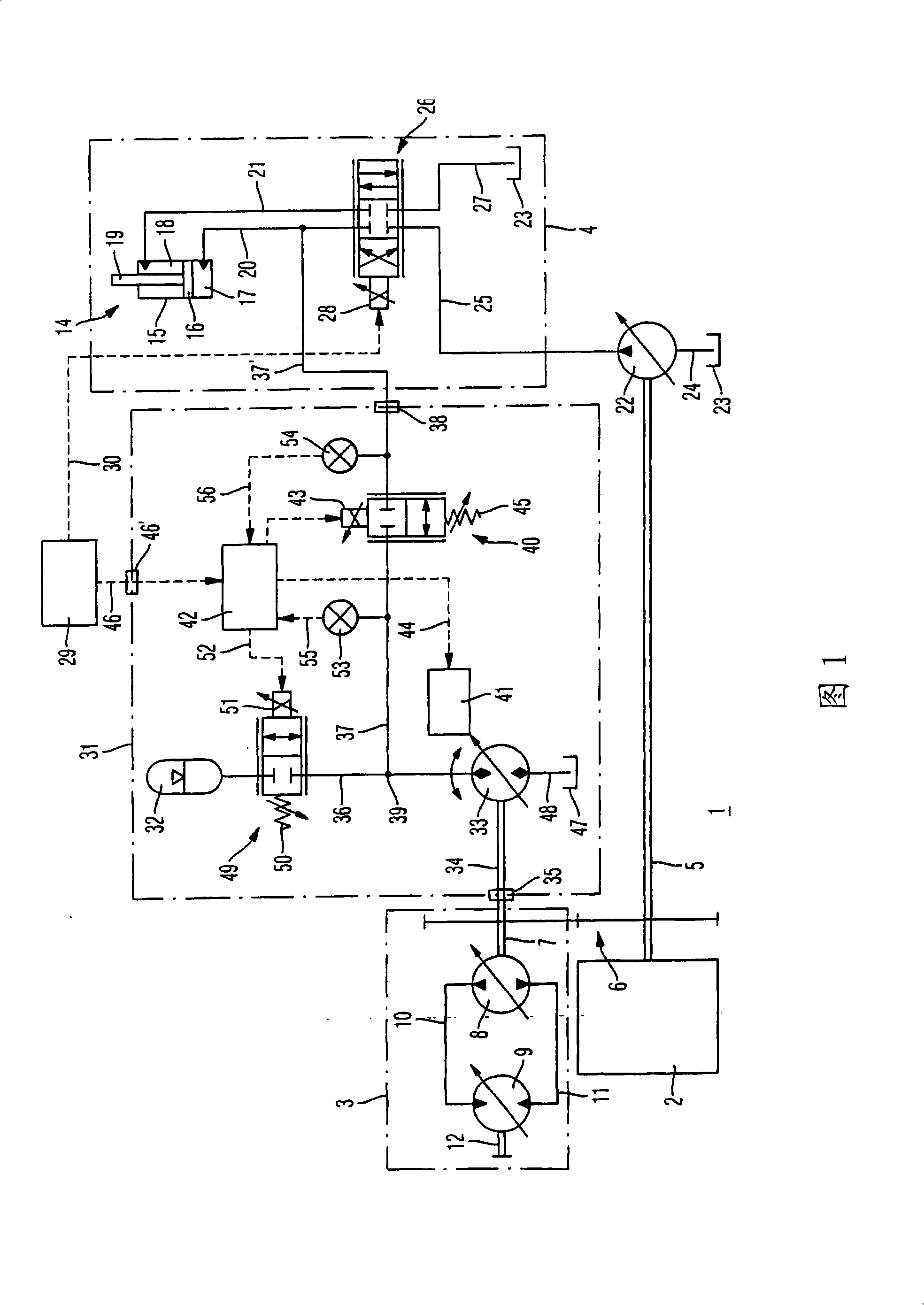
[0019] figure 1 The illustration shows a drive system 1 comprising, for example, a diesel internal combustion engine 2 as main drive machine. A diesel internal combustion engine 2 is connected to the mechanical part of the drive system 1 comprising a hydrostatic transmission 3 in the illustrated exemplary embodiment. Moreover, the diesel internal combustion engine 2 is connected to the hydrostatic part of the drive system, the components of which are in the figure 1 is illustrated as a whole with the reference number 4 . To drive the hydrostatic transmission 3 and the hydrostatic part 4 of the drive system 1 , the diesel internal combustion engine 2 drives a drive shaft 5 . The drive shaft 5 cooperates directly with the hydrostatic part 4 of the drive system 1 and drives a hydraulic pump 22 there. The drive shaft 5 is connected via a transmission stage 6 to a transmission input shaft 7 of the hydrostatic transmission 3 .

[0020] The hydrostatic transmission 3 comprises a ...


PUM


Abstract

The invention relates to an energy storage unit for a hydrostatic-mechanical drive system (1). The energy storage unit (31) comprises at least one hydrostatic machine (33) which can be connected to the drive system (1) via a mechanical interface (35). Furthermore, the energy storage unit (31) comprises a storage element (32) which is connected to a hydrostatic machine (33) via a storage line (36). The storage line (36) can be connected to a hydraulic interface (38), and the hydraulic interface (38) is provided for the purpose of connecting the energy storage unit (1) to the drive system (1).

Description

technical field [0001] The invention relates to an accumulator unit for a hydrostatic mechanical drive system. Background technique [0002] A hydrostatic drive for a motor vehicle and a method for operating the drive are known from AT 395960B. The hydrostatic drive comprises a drive motor with a hydrostatic pump designed as a fixed displacement pump. The hydrostatic pump is connected to a hydraulic motor for driving the vehicle through a first working line and a second working line. An accumulator element is in any case connected to both working lines, so that, in the case of overrunning of the vehicle, the hydraulic motor, thanks to its pumping action, is able to fill the accumulator element and thus in the form of pressure energy Accumulate kinetic energy. [0003] In order to recover the accumulated energy, the pressure medium accumulated in the accumulator element is fed back into the circuit and drives the hydraulic motor. [0004] A disadvantage of said system is ...

Claims


Application Information

Patent Timeline
IPC IPC(8): B60K6/12
CPCB60K6/12Y02T10/6208F15B1/024F15B2211/20523F15B2211/20546F15B2211/20569F15B2211/212F15B2211/6306F15B2211/6313F15B2211/88Y02T10/62
Inventor 塞波·蒂卡宁塞巴斯蒂安·奥施曼
Owner ROBERT BOSCH GMBH
Why Eureka
Try Eureka