Coding/decoding methods, coders/decoders, and method and device for finding optimally matched modules

A best matching and encoder technology, applied in the field of image coding, can solve the problems of not being able to improve coding efficiency better, and not being able to eliminate residual image correlation

Active Publication Date: 2009-08-26
HUAWEI TECH CO LTD +1
View PDF0 Cites 5 Cited by
  • Summary
  • Abstract
  • Description
  • Claims
  • Application Information

AI Technical Summary

Problems solved by technology

In fact, in the field of multi-view video, there is still a strong correlation between the residual image generated after one prediction of the current image to be encoded and the residual image corresponding to the reference image. When the images of a video sequence are encoded, the correlation between the residual images cannot be eliminated, so the encoding efficiency cannot be better improved.

Method used


Image

  • Coding/decoding methods, coders/decoders, and method and device for finding optimally matched modules
  • Coding/decoding methods, coders/decoders, and method and device for finding optimally matched modules
  • Coding/decoding methods, coders/decoders, and method and device for finding optimally matched modules

Examples


Embodiment 1

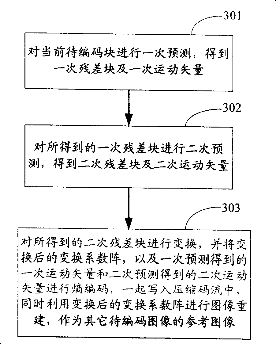
[0092] In this embodiment, the implementation manner in the first manner is described in detail. That is, the secondary prediction is directly performed on the primary residual image generated by the primary prediction, and the subsequent encoding process is performed on the secondary residual image generated by the secondary prediction. image 3 It is a flow chart of the image encoding method in Embodiment 1 of the present invention. In general, when inter-frame prediction is performed on the original image of the current image to be encoded, the prediction is performed in units of macroblocks or blocks, and the last block carries the end of the current image to be encoded, and then starts Perform the same inter-frame prediction on the next image to be encoded. Therefore, the flow of the image encoding method in this embodiment takes the encoding process of a macroblock of the image currently to be encoded as an example to describe the encoding method of the present inventio...

Embodiment 2

[0155] In this embodiment, the implementation of the second method is described in detail, that is, before the secondary prediction, the primary residual image is first transformed, and then the transformed primary residual image is converted to the secondary reference image corresponding to Secondary prediction is performed on the transformed secondary reference image, and subsequent encoding processing is performed on the secondary residual image generated after the secondary prediction.

[0156] In this embodiment, in order to distinguish it from method 1, the primary residual image generated after transforming the primary residual image is called the primary residual image transformation coefficient matrix, and correspondingly, the primary residual image generated after transforming the primary residual block is The primary residual block is called the primary residual block transformation coefficient matrix, and the secondary residual image generated by performing secondar...

Embodiment 3

[0210] In this embodiment, the image encoding method and decoding method in Embodiment 1, and the image encoding method and decoding method in Embodiment 2 can be applied simultaneously. Correspondingly, the encoder and the decoder have both the implementation functions of the encoder and the decoder in the first and second embodiments above, and the implementation in the first embodiment is added on the basis of the second embodiment . Figure 15 It is a schematic structural diagram of the encoder in Embodiment 3 of the present invention. The encoder includes: a primary prediction module, a transformation module, a secondary prediction module, an encoding module, a secondary reconstruction module, an inverse transformation module and a primary reconstruction module. It includes the encoding process represented by the dotted line: the current image to be encoded→primary prediction module→secondary prediction module→transformation module→encoding module→code stream; reconstruc...


PUM


Abstract

The invention discloses two coding methods. One coding method comprises the steps of: performing a first prediction of a current image to be coded to obtain a first residual image and a first motion vector; and performing a second prediction to the first residual image to obtain a second residual image and a second motion vector and writing the second residual image, the second motion vector and the first motion vector into a compression code flow or into compression code flow after entropy coding. The invention also discloses two decoding methods, two coders, two decoders, a coding method, a coder-decoder, a method and a device for finding optimally matched modules from a plurality of multilook images. The technical proposal of the invention can eliminate the relevance of residual images.

Description

technical field [0001] The present invention relates to image coding technology in the field of multimedia, in particular to an image coding method, a decoding method, a coder, a decoder, a codec method, a codec, and a method and device for finding the best matching block among multi-view images. Background of the invention [0002] Current video coding standards such as the H.261, H.263, H.263+, and H.264 standards formulated by the International Telecommunication Union (ITU, International Telecommunication Union), and the standards established by the Moving Picture Experts Group (MPEG, Moving Picture Experts Group) MPEG-1, MPEG-2, MPEG-3, MPEG-4, etc. are all based on the hybrid coding (Hybrid Coding) framework. The so-called hybrid coding framework is a video image coding method that mixes time and space. When coding, first perform intra-frame and inter-frame prediction to obtain the predicted value to eliminate the correlation in the time domain; then according to the pr...

Claims


Application Information

Patent Timeline
Patent Type & Authority Applications(China)
IPC IPC(8): H04N7/28H04N19/94
CPCH04N19/00781H04N19/00278H04N7/26244H04N7/26106H04N7/362H04N7/50H04N7/26324H04N19/00363H04N19/00121H04N19/00733H04N19/0069H04N19/00587H04N7/26867H04N7/2676H04N19/13H04N19/176H04N19/194H04N19/51H04N19/517H04N19/61
Inventor 何芸许晓中郑建铧孟新建史舒娟郑萧桢
Owner HUAWEI TECH CO LTD
Why Eureka
Try Eureka