Vanishing point detecting device and detecting method

A detection device and detection method technology, applied in character and pattern recognition, instruments, computer components, etc., can solve problems such as complex perspective deformation, and achieve the effect of overcoming the shortcomings of instability

Inactive Publication Date: 2009-09-02
FUJITSU LTD
View PDF3 Cites 22 Cited by
  • Summary
  • Abstract
  • Description
  • Claims
  • Application Information

AI Technical Summary

Problems solved by technology

However, due to different models of digital cameras and webcams and different shooting angles, perspective distortion is very complicated (especially for document images captured by mobile phone cameras

Method used


Image

  • Vanishing point detecting device and detecting method
  • Vanishing point detecting device and detecting method
  • Vanishing point detecting device and detecting method

Examples


Embodiment approach 1

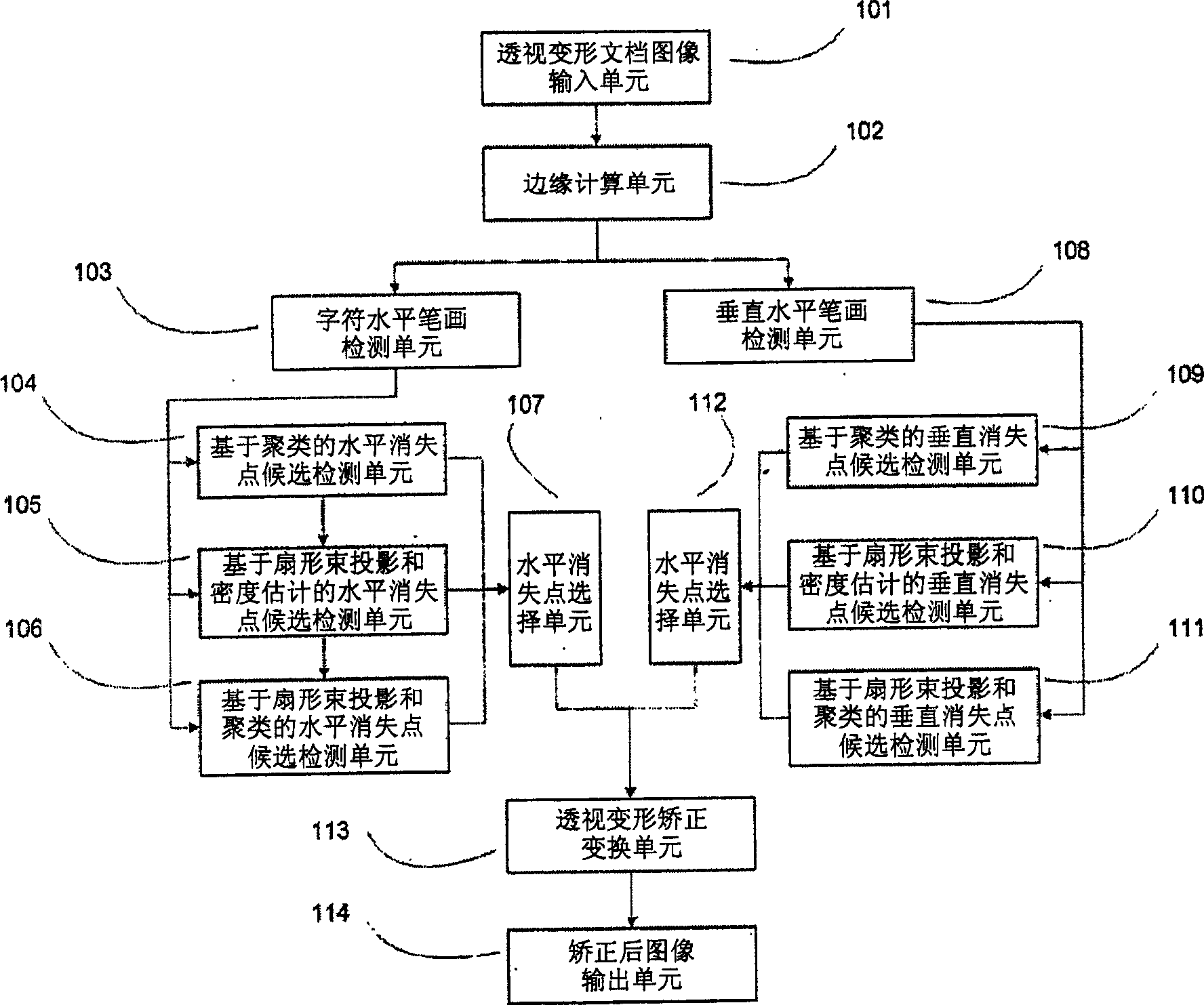
[0129] In the above example, if figure 1 As shown, the horizontal vanishing point detection units 104, 105, and 106 only use the horizontal line segments obtained by the character horizontal stroke detection unit 103, but they can also use other methods in addition to the horizontal line segments obtained by the character horizontal stroke detection unit 103 Get the horizontal line segment. For example, the long horizontal line segment (direct horizontal line segment) obtained by performing connected domain analysis on the edge image and the corresponding horizontal line segment obtained through text line detection (indirect horizontal line segment). In addition, only the direct horizontal line segment and the indirect horizontal line segment may be used, instead of the horizontal line segment obtained by the character horizontal stroke detection unit 103 (although strictly speaking, it is also a kind of indirect horizontal line segment).

[0130] Similarly, for the vertical ...

Embodiment approach 2

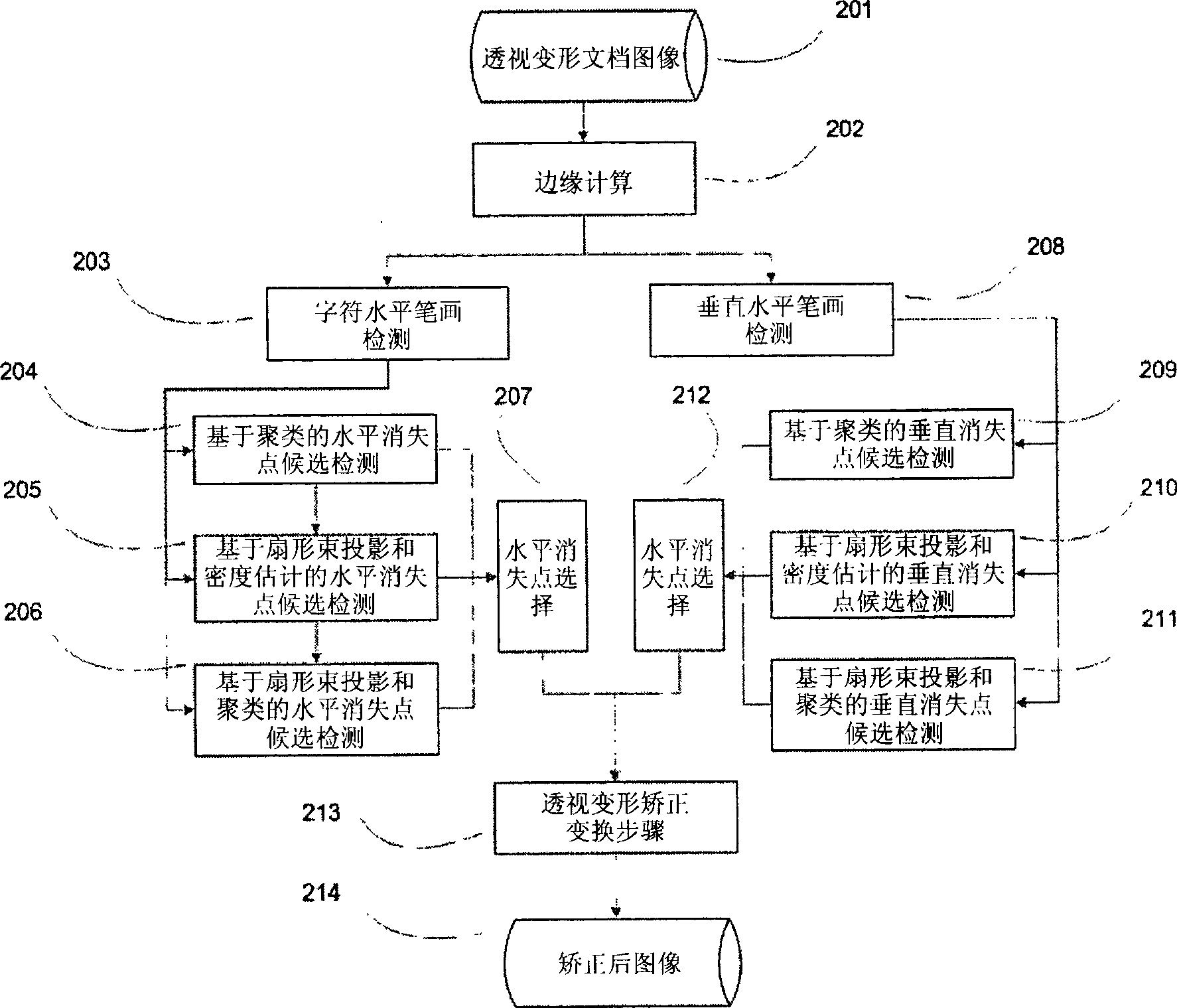
[0132] Although in the above embodiments, the horizontal vanishing point detection units 104 , 105 , and 106 are integrated into one device for centralized description, only one or two of them may be included in one device. When only one of them is included, there is no need figure 1 The horizontal vanishing point selection unit 107 can simplify the structure of the device.

[0133] Likewise, only one or two of the vertical vanishing point detection units 109 , 110 , 111 may be included in one device.

Embodiment approach 3

[0135] Although the above components are drawn separately and independently, this is only schematic. They can be physically integrated, separated, or partially integrated. Units or modules with the same function can be realized by the same physical device or logical module.

[0136] Although the above steps are described separately and sequentially, their execution order can be adjusted, and they can also be executed in parallel.


PUM


Abstract

The invention provides a vanishing point detecting device and a detecting method, and the vanishing point detecting device comprises a line segment detecting unit used for obtaining a horizontal line segment or a vertical line segment of an input image, an intersection point set obtaining device used for obtaining the intersection point set of the horizontal line segment or an intersection point set of the vertical line segment, a candidate vanishing point detecting unit used for determining a candidate vanishing point, and a vanishing point determining unit used for determining a final vanishing point according to the candidate vanishing point determined by the candidate vanishing point detecting unit; wherein the candidate vanishing point detecting unit is one or more of the following: a candidate vanishing point detecting unit based on fanning beam projection and density estimation, which carries out fanning beam projection to the input image and takes the intersection point with the highest point density in a high-density fanning beam area as the candidate vanishing point; a candidate vanishing point detecting unit based on fanning beam projection and clustering, which carries out the fanning beam projection, obtains a plurality of clustering of the intersection points in the high-density fanning beam area and takes the center of each clustering as the candidate vanishing point.

Description

technical field [0001] The present invention relates to an apparatus and method for correcting perspective distortion of document images, especially images containing a small amount of text. More particularly, it relates to a method and apparatus for detecting a vanishing point based on character horizontal strokes and a method and apparatus for detecting a vanishing point using fan beam projection. Background technique [0002] Correcting the perspective distortion of document images based on digital cameras is an important step in document analysis and recognition. The meaning of the perspective distortion correction operation is to convert an image with perspective distortion into an image without perspective distortion. [0003] The principle of perspective distortion correction of various document images can be found in P.Clark, M.Mirmehdi's article "Rectifying perspective views oftext in 3D scenes using vanishing points." in Pattern Recognition 36(11), 2003, M.Pilu at...

Claims


Application Information

Patent Timeline
IPC IPC(8): G06K9/72G06K9/62G06V20/00G06V10/44
CPCG06K9/4604G06K9/00624G06V20/00G06V10/44
Inventor 殷绪成孙俊藤井勇作原伸之藤本克仁直井聪
Owner FUJITSU LTD
Why Eureka
Try Eureka