
Liquid crystal display splicing wall

A technology of liquid crystal display and liquid crystal display unit, applied in static indicators, instruments, etc., can solve problems such as bandwidth waste, achieve the effect of reducing wiring, enhancing flexibility and scalability

Active Publication Date: 2009-09-02
KUSN INFOVISION OPTOELECTRONICS
View PDF0 Cites 34 Cited by
  • Summary
  • Abstract
  • Description
  • Claims
  • Application Information

AI Technical Summary

Problems solved by technology

However, in practical applications, the screens of some LCD units may be the same, or even some LCD units have no display screen at all, which causes a waste of bandwidth.

Method used


Image

  • Liquid crystal display splicing wall
  • Liquid crystal display splicing wall
  • Liquid crystal display splicing wall

Examples


Embodiment Construction

[0014] In order to make the purpose, technical solution and advantages of the present invention clearer, the present invention will be further elaborated below in conjunction with the accompanying drawings.

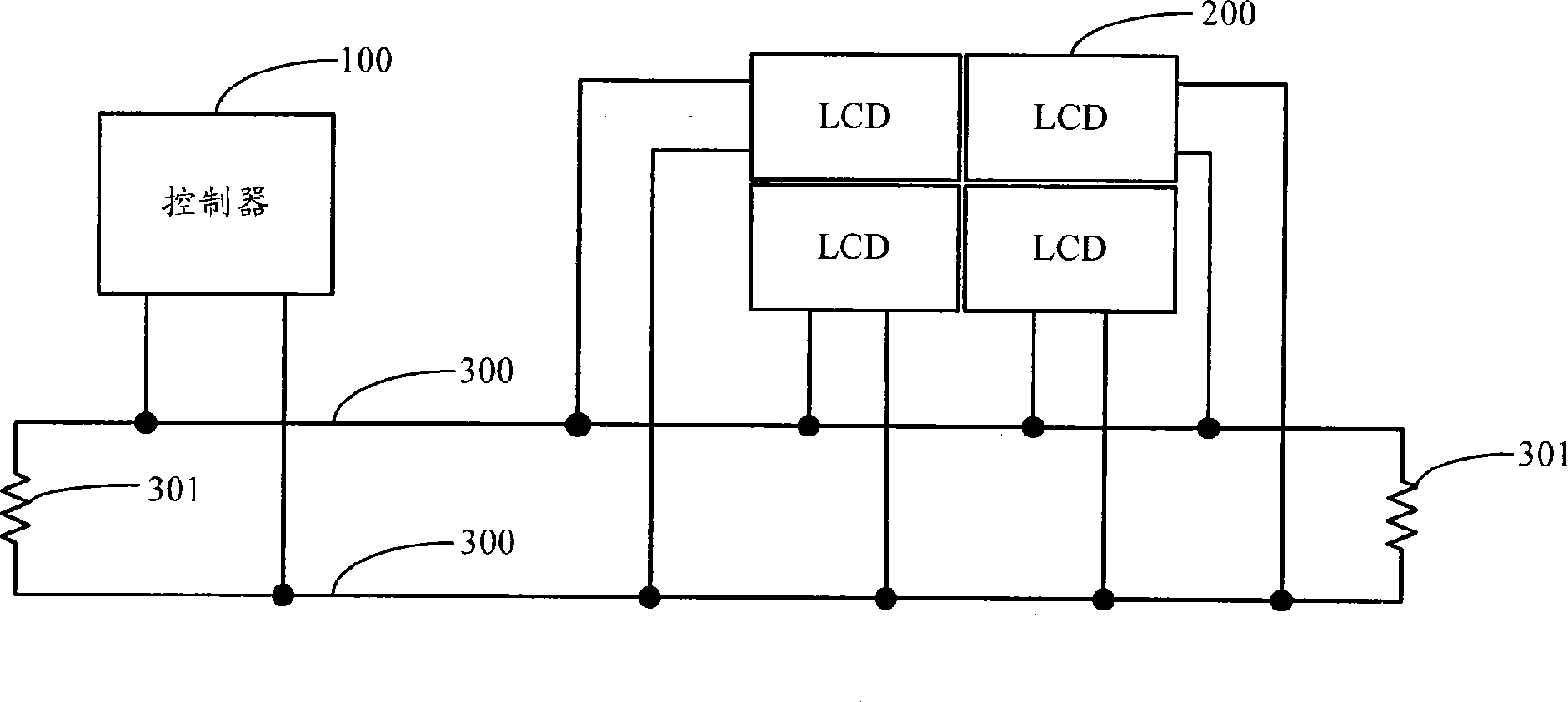
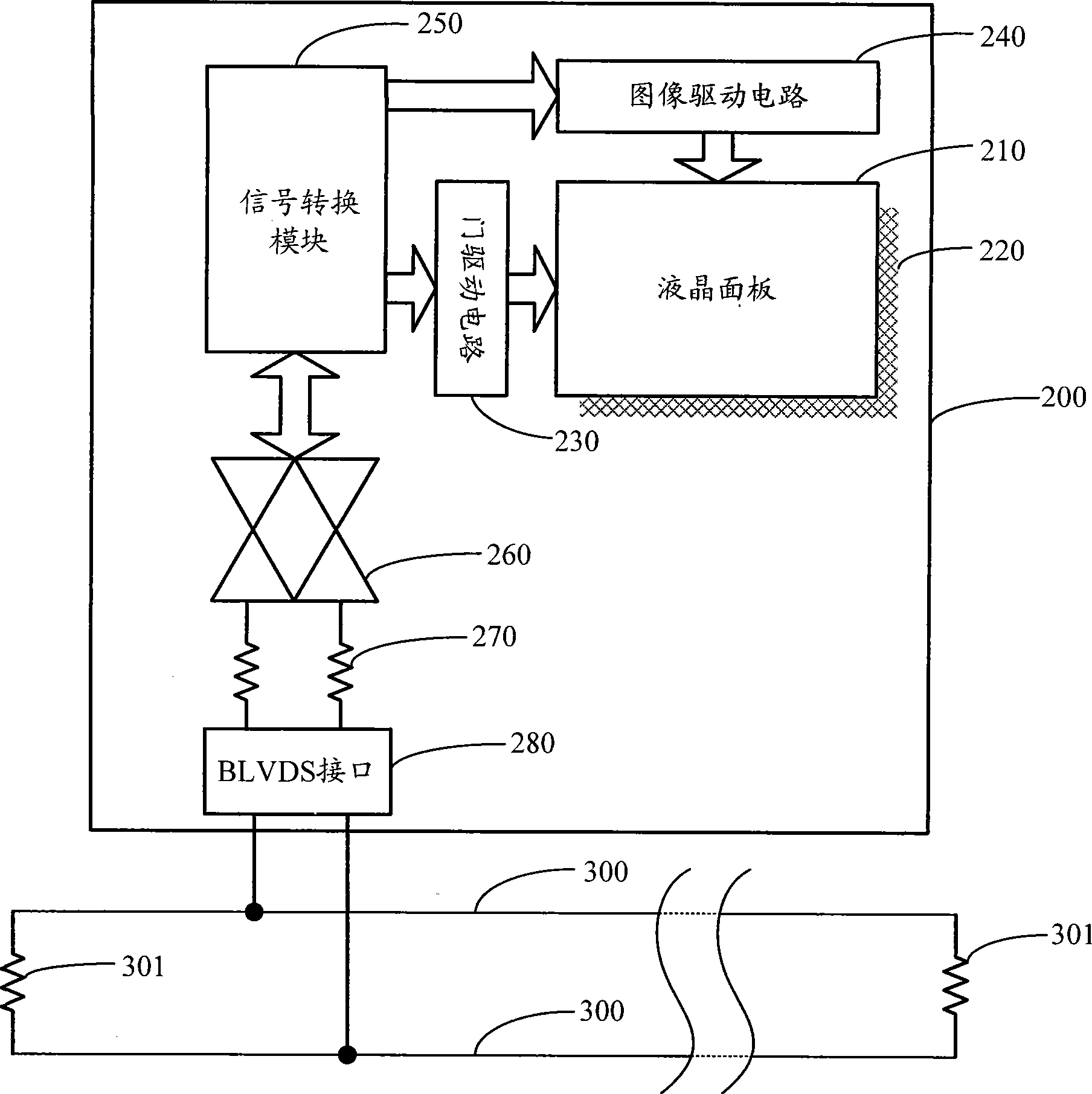
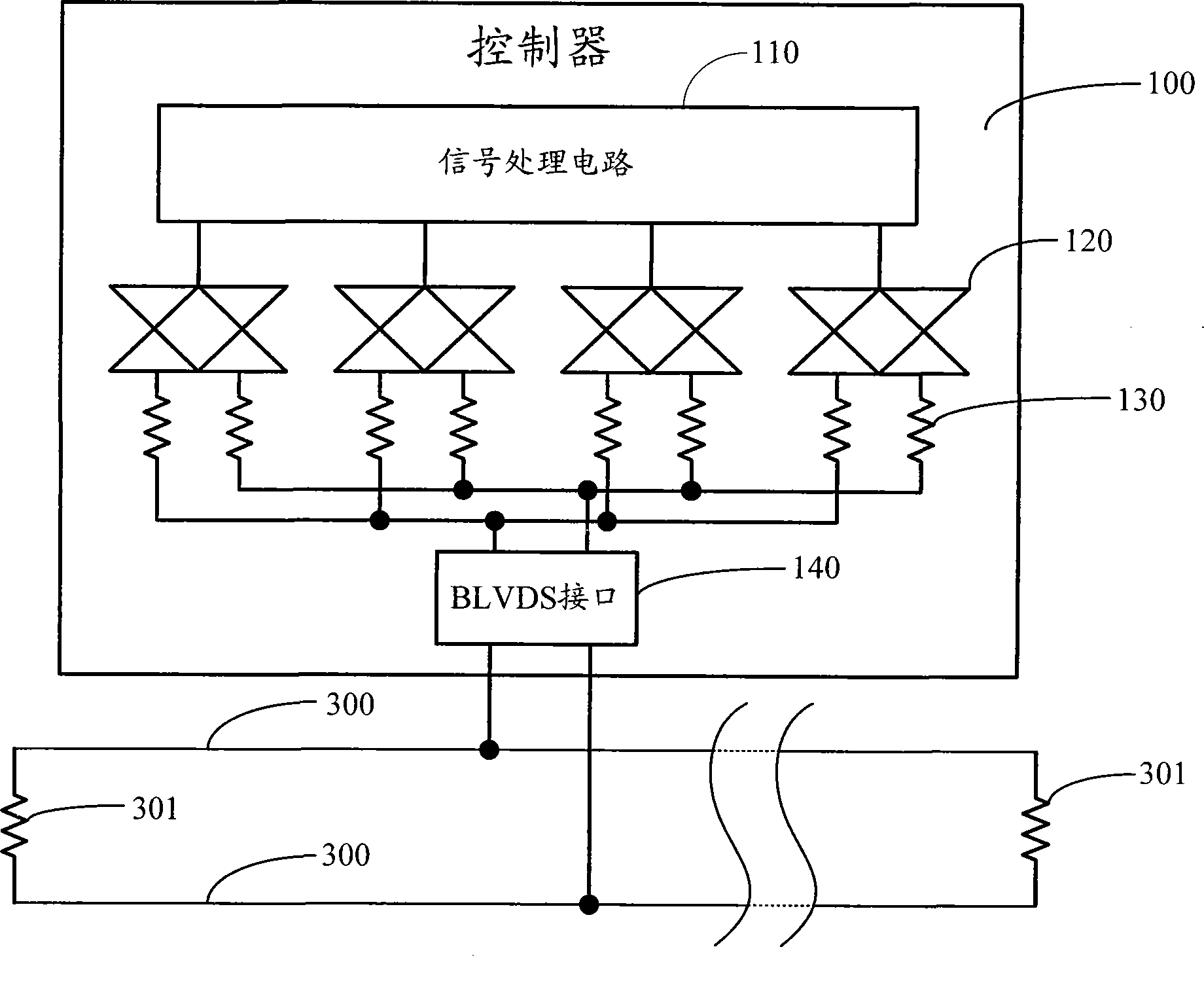
[0015] figure 1 A structure diagram of a liquid crystal display splicing wall according to an embodiment of the present invention is given. The LCD video wall includes at least two liquid crystal display units (LCD) 200 , a controller 100 , and a low voltage differential signal bus (Low Voltage Differential SignalBus, BLVDS) 300 connecting the LCD units 200 and the controller 100 . Both the liquid crystal display unit 200 and the controller 100 have a BLVDS interface. exist figure 1 The liquid crystal display splicing wall in the figure includes four liquid crystal display units 200 as an example, each liquid crystal display unit 200 is connected to the BLVDS bus 300 through its own BLVDS interface, and the controller 100 is also connected to the BLVDS bus 300 through t...


PUM


Abstract

The invention discloses a liquid crystal display splicing wall which comprises a controller (100) and more than two liquid crystal display units (200), wherein the controller (100) and the liquid crystal display units (200) are connected to a BLVDS bus (300) by respective bus low voltage differential signaling (BLVDS) interfaces, and each liquid crystal display unit has an exclusive bus address; the controller (100) distributes an image signal of each liquid crystal display unit, encapsulates the image signal and the bus address of the liquid crystal display unit (200) which corresponds to the image signal into a data packet and sends the data packet to the BLVDS bus (300) by the BLVDS interfaces; the liquid crystal display units (200) judge whether the bus address of the data packet in the BLVDS bus (300) is matched with the bus address of the liquid crystal display units or not, if the bus address of the data packet in the BLVDS bus (300) is matched with the bus address of the liquid crystal display units, the LCD display units receive the data packet and display images according to the image signals in the data packet.

Description

technical field [0001] The invention relates to the technical field of display and video output, in particular to a liquid crystal display splicing wall. Background technique [0002] With the rapid development of the commercial and advertising industry, in some special occasions, such as outdoor advertisements, squares, stations, stadiums, shopping malls, studios, large conference rooms, etc., in order to provide large-screen display effects and satisfy users to watch from a distance To meet the needs of clear images, it is often necessary to install a large-sized display device. However, the current image display devices, such as TVs and monitors, are difficult to achieve such a large size, so a large-area display system is usually used to splice multiple large-screen TVs or monitors in rows and columns, that is, a display splicing wall ( Display Wall). Each display device that makes up the display splicing wall is called a display unit, which can be a ray tube display (...

Claims


Application Information

Patent Timeline
IPC IPC(8): G09G3/36
Inventor 司秉玉
Owner KUSN INFOVISION OPTOELECTRONICS
Learn More