
Package structure of light emitting diode and the packaging method thereof

A technology of light-emitting diodes and packaging methods, applied in electrical components, electric solid-state devices, circuits, etc., can solve the problems of affecting the light emission angle, limiting the light emission angle, etc., and achieve the effect of easy control and wide light emission angle

Inactive Publication Date: 2011-07-13
LEDTECH ELECTRONICS CORP
View PDF0 Cites 0 Cited by
  • Summary
  • Abstract
  • Description
  • Claims
  • Application Information

AI Technical Summary

Problems solved by technology

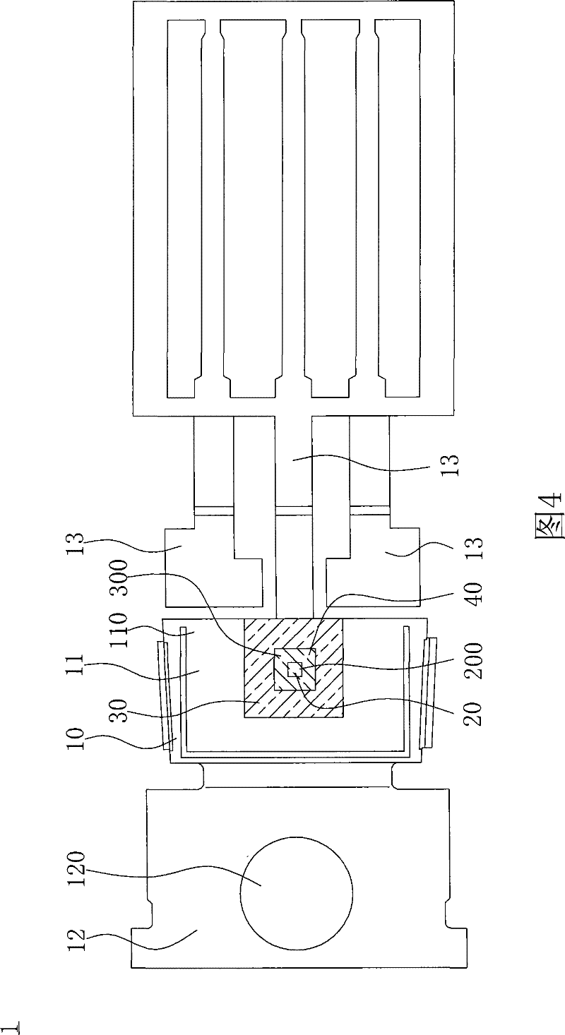
Wherein the substrate 10c has a packaging surface 100c and a groove 101c formed on the packaging surface 100c, the light emitting diode 12c is accommodated in the groove 101c, and is electrically connected to the substrate 10c by means of a flip chip, and the fluorescent colloid 11c can be uniformly housed in the groove 101c to encapsulate the surrounding of the light emitting diode 12c; however, since the light emitting diode 12c is housed in the groove 101c, it will inevitably affect the emission angle of the light, so that the light is limited by the size of the groove 101c , thereby limiting its luminous angle

Method used


Image

  • Package structure of light emitting diode and the packaging method thereof
  • Package structure of light emitting diode and the packaging method thereof
  • Package structure of light emitting diode and the packaging method thereof

Examples


Embodiment Construction

[0046] see Figure 4 and Figure 5 , which shows a schematic plan view and a side view of a preferred embodiment of the packaging structure of the light emitting diode of the present invention. As shown in the figure, the LED packaging structure 1 of this embodiment includes: a substrate 10 , a LED unit 20 , a light-transmissive filling fixing seat 30 and a colloid unit 40 .

[0047] Such as Figure 4 and Figure 5 As shown, the substrate 10 can be made of aluminum substrate, copper substrate or silver substrate. In this embodiment, the substrate 10 is a diode support structure, and its material is a copper substrate. The substrate 10 has a main body portion 11, a top portion 12 and a pin portion 13, and the top portion 12 and the pin portion 13 can be respectively formed on two opposite ends of the main body portion 11; wherein, the main body portion 11 has a The packaging surface 110 for accommodating the LED unit 20 and the glue unit 40, the top 12 has a pair of alignm...


PUM


Abstract

The invention discloses a package method of a light emitting diode (LED), comprising the following steps: providing a pre-molded base plate; forming a translucidus filling fixed seat on the base plate, a receiving groove being arranged in the translucidus filling fixed seat; an LED unit being arranged in the receiving groove of the ranslucidus filling fixed seat, and the LED unit being electrically connected to the base plate, wherein the translucidus filling fixed seat is formed by pressing a pressing device on the base plate through a pressing mode, and the receiving groove is formed by removing the pressing device; and filling the receiving groove of the filling fixed seat with a colloid unit, through the receiving groove, the colloid unit being controllably and uniformly distributed on the LED surface and circumference. Though the design of the invention, the amount of the colloid unit can be easily controlled, and the light emitted by LED unit can pass through the translucidus filling fixed seat, thus achieving a broad light emitting angle.

Description

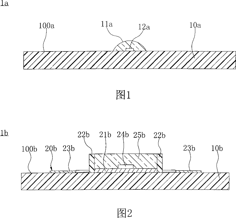
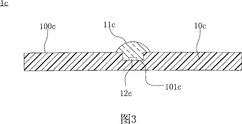
technical field [0001] The present invention relates to a packaging structure and a packaging method thereof, in particular to a packaging structure of a light-emitting diode and a packaging method thereof. By forming a light-transmitting fixing seat on the surface of a substrate to accommodate colloids, the colloids can be controlled and Evenly cover the surface of the LED. Background technique [0002] see figure 1 , which is a schematic diagram of a conventional packaging structure of a light emitting diode. The packaging structure 1a of the light emitting diode includes: a substrate 10a, a fluorescent colloid 11a and a light emitting diode 12a. The fluorescent colloid 11a and the light-emitting diode 12a are respectively arranged on the packaging surface 100a of the substrate 10a. In the existing packaging technology of the light-emitting diode, the fluorescent colloid 11a is correspondingly packaged on the surface of the light-emitting diode 12a and Around, in order ...

Claims


Application Information

Patent Timeline
Patent Type & Authority Patents(China)
IPC IPC(8): H01L25/00H01L25/075H01L33/00H01L23/13H01L23/498H01L23/31H01L21/50H01L21/56H01L21/60H01L21/48
Inventor 郭瑞伦王耀毅王方波
Owner LEDTECH ELECTRONICS CORP
Learn More