Tile type magnetic-fluxleakage permanent magnet electric motor

A technology of permanent magnets and magnetic flux leakage, which is applied in the direction of electrical components, electromechanical devices, and static parts of magnetic circuits, can solve problems such as failure to generate, and achieve high power-saving effects

Inactive Publication Date: 2009-09-02
罗永
View PDF4 Cites 3 Cited by
  • Summary
  • Abstract
  • Description
  • Claims
  • Application Information

AI Technical Summary

Problems solved by technology

However, as we all know, the magnetic field of a permanent magnet is a static magnetic field, and its magnetic poles are fixed; within a same pole pitch, the repulsive and attractive forces of the same and different magnetic poles within their magnetic field range are equal, that is, in the absence of equal In the state of alternating electromagnetic field and external force of magnetic flux and magnetic flux density, it is impossible for the permanent magnet rotor to generate a directional magnetomotive force greater than the required power consumption in the permanent magnet stator magnetic field, saving electric energy to a greater extent

Method used


Image

  • Tile type magnetic-fluxleakage permanent magnet electric motor
  • Tile type magnetic-fluxleakage permanent magnet electric motor
  • Tile type magnetic-fluxleakage permanent magnet electric motor

Examples


Embodiment Construction

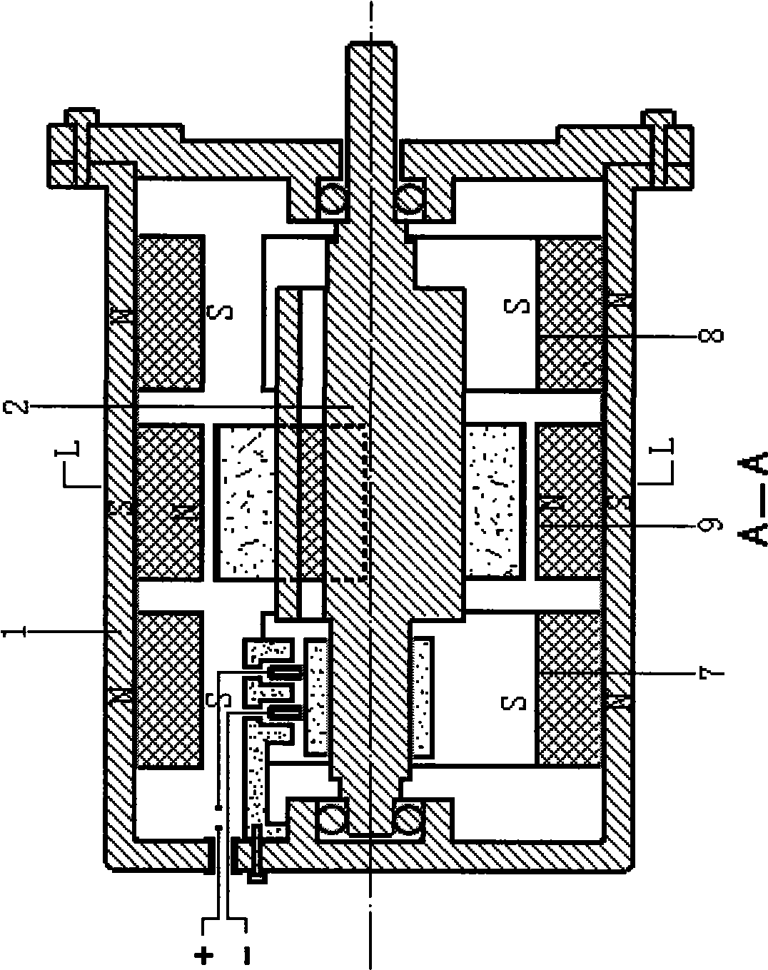
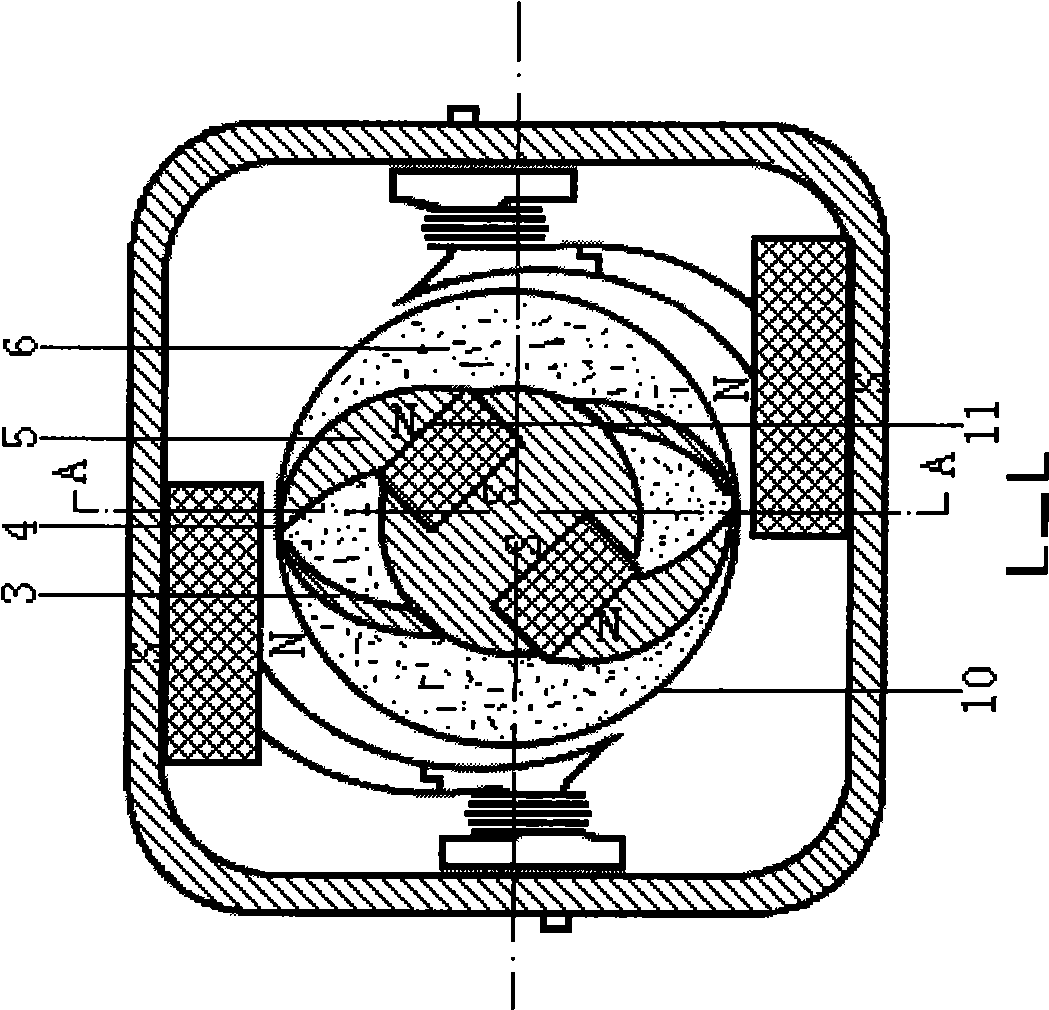
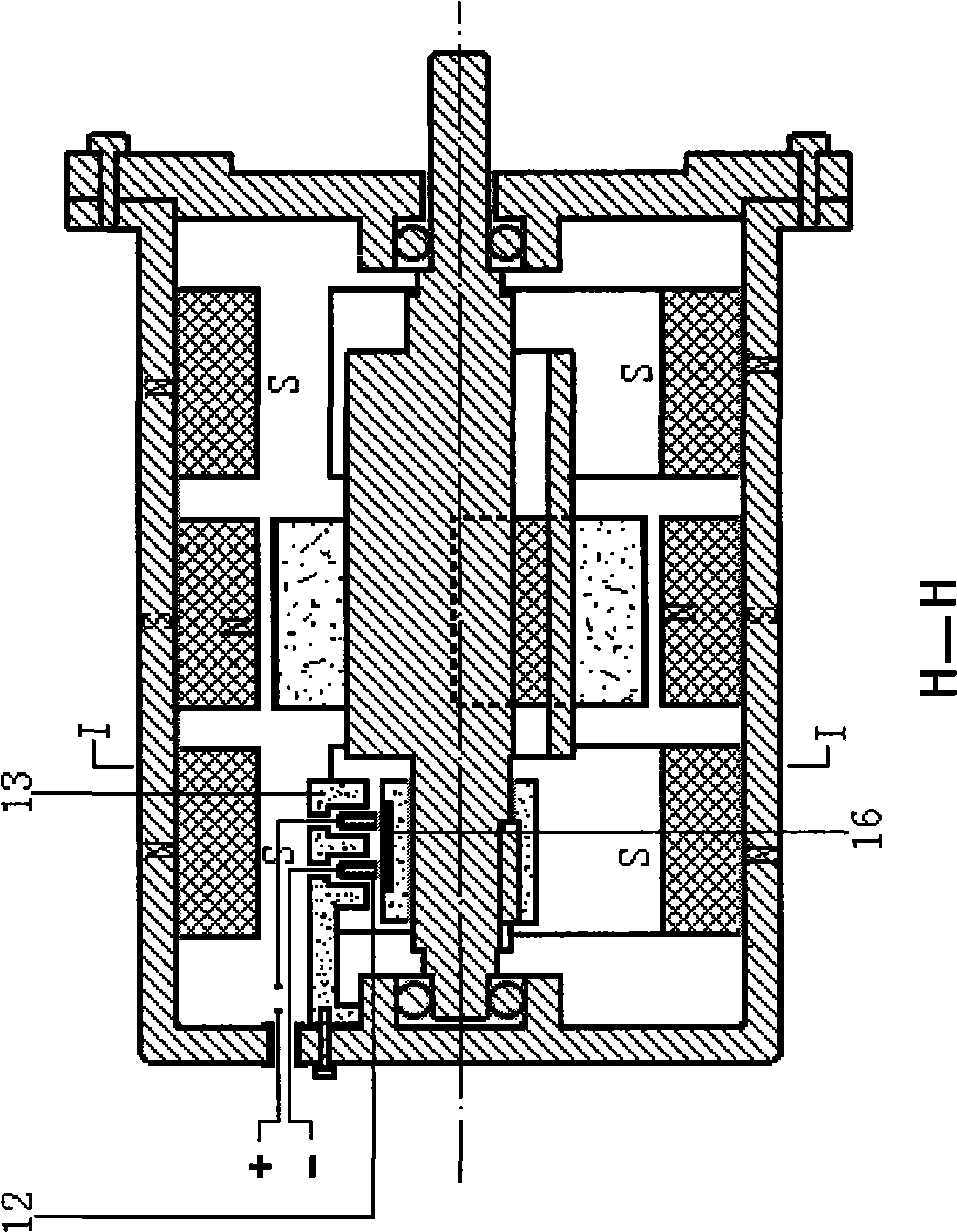
[0012] A tile-type flux leakage permanent magnet motor comprises a stator (1), a rotor (2), a DC electromagnetic coil and accessories. It is characterized in that: the permanent magnet pole face of the rotor is a rectangular permanent magnet facing inward and outward, which is fixed in the groove of the iron rotor; , the filling epoxy resin (6) is solidified, and the outer edge turns of the non-magnetic metal wire (10) are fixed, and the tile tip (4) is oriented to the direction of the magnetomotive force. The stator permanent magnet poles are fixed in three equal-sized, axially parallel, spaced apart, and the magnetic pole faces are rectangular permanent magnets facing inward and outward. It is the same-pole stator permanent magnet pole face (9), which is parallel to the width of the rotor tip tile-shaped leakage flux blunt iron (5). figure 1 ), the inner faces of the permanent magnets on both sides are the permanent magnet pole faces (7, 8) of the heteropolar stator, and th...


PUM


Abstract

The invention provides a tile type magnetic-fluxleakage permanent magnet electric motor, comprising a stator, a rotor, a direct current (DC) magnetic coil and an accessory. The poleface of the permanent-magnet pole of the rotor has the same pole as the poleface and the polarity which are printed at the centre of the stator; and the two sides of the rotor are the magnetic poles of the permanent magnet with the same standard of the heterospolar of the stator. A sharp tile-shaped magnetic-fluxleakage passive iron is fixed on the poleface of the permanent-magnet pole of the rotor so that a main magnetic circuit thereof is a tile-shaped magnetic-fluxleakage magnetic field; two pieces of tile-shaped magnetic-fluxleakage passive irons and magnetizer of DC coil polariton are fixed on the poleface of the permanent-magnet pole of heteropolar stator at the two sides so that the magnetic potential thereof rises to pole terminal; and non kinematic potential is produced when the sharp tile-shaped magnetic-fluxleakage passive iron of the rotor enters the poleface of the permanent-magnet pole, and orientated magnetic kinematic potential from the poleface to the pole terminal is produced when the sharp tile-shaped magnetic-fluxleakage passive iron of the rotor enters the half of the poleface of the permanent-magnet pole. Electromagnetic field with the same polarity which is produced on the pole terminal shields the magnetic-fluxleakage magnetic resistance, resumes the state without magnetic kinematic potential and switches off when entering the next orientated magnetic kinematic potential magnetic field. The orientated magnetic kinematic potential of the electric motor is larger than the magnetic-fluxleakage magnetic resistance when the electric motor is out of service; and the electricity-saving rate is extremely high.

Description

Technical field: [0001] The name of the invention relates to a motor device in which the magnetic poles of the stator and the rotor are both permanent magnets. Background technique [0002] Permanent magnets have permanent magnetic energy. At present, the application of permanent magnet energy in kinetic energy is mainly to use the alternating electromagnetic field in the motor and act on the static magnetic field of the permanent magnet, so that the rotor of the motor rotates directionally under the action of magnetic field repulsion and suction to achieve the purpose of saving electricity. If the permanent magnetic energy inherent in permanent magnets can be fully utilized, the directional magnetomotive force can be generated in the permanent magnet rotor in the magnetic field of the permanent magnet stator, and the continuous directional rotation with a small amount of electromagnetic field can be assisted, it will undoubtedly save more money needed for social development...

Claims


Application Information

Patent Timeline
IPC IPC(8): H02K25/00H02K1/27H02K1/12H02K1/17
Inventor 罗永
Owner 罗永
Why Eureka
Try Eureka