Resolution method and resolver for signals of rotating transformer

A resolver and angle signal technology, applied in the solver field, can solve the problems of high cost, high price, cost reduction, etc., and achieve the effect of cost reduction

Inactive Publication Date: 2010-10-13
NORTHWESTERN POLYTECHNICAL UNIV
View PDF3 Cites 0 Cited by
  • Summary
  • Abstract
  • Description
  • Claims
  • Application Information

AI Technical Summary

Problems solved by technology

[0005] In order to overcome the disadvantages of high price and high cost in the prior art, the present invention provides a resolver signal solution method applied in a high-precision servo system, which adjusts the output of the resolver in real time and outputs a digital signal processor Recognizable signal, and then calculate the actual position of the rotor through the digital signal processor, and at the same time can judge the rotation direction of the rotor, which not only meets the high precision requirements of the servo system, but also greatly reduces the cost

Method used


Image

  • Resolution method and resolver for signals of rotating transformer
  • Resolution method and resolver for signals of rotating transformer

Examples


Embodiment Construction

[0030] Method embodiment, comprises the following steps:

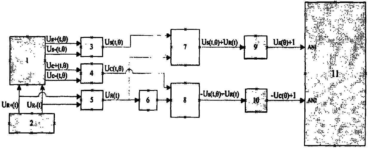
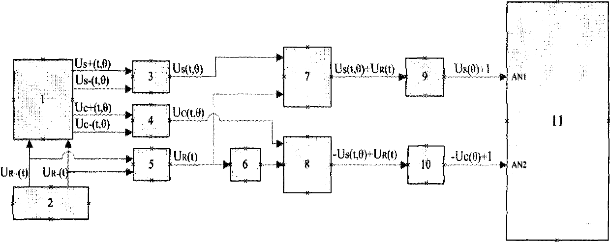
[0031] 1) Rotate the motor for a full cycle, collect the rotation angle signal fed back by the resolver installed on the motor shaft, and obtain the peak and valley values ​​of the rotation angle signal waveform. The sine table of 0~1 / 4 cycle is stored in it, its amplitude is 2048~4095, and the corresponding angle is 0~90°, for reference table and interpolation calculation.

[0032] 2) Sampling the current low-frequency sine signal Us(θ) and low-frequency cosine signal Uc(θ) and converting these two angle values ​​into digital quantities respectively as X and Y, and simultaneously saving and backing up the current X and Y as X_bak and Y_bak respectively, Compare with the next sampling result to judge the direction of rotor rotation.

[0033] 3) Divide the angular position θ of the rotor into four quadrants, namely 0-90°, 90°-180°, 180°-270°, 270°-360°, and determine the quadrant of the rotor position according to the ...


PUM


Abstract

The invention discloses a resolution method and a resolver for signals of a rotating transformer. The method comprises the steps of: acquiring a rotating angle signal of a motor and establishing a sinThe invention discloses a resolution method and a resolver for signals of a rotating transformer. The method comprises the steps of: acquiring a rotating angle signal of a motor and establishing a sinl signal processor; and a cosinoidal differential signal feedback by the rotating transformer passes through another differential signal converter, then is input into the precision absolute value addel signal processor; and a cosinoidal differential signal feedback by the rotating transformer passes through another differential signal converter, then is input into the precision absolute value adder along with the sinusoidal excitation signal which passes through a phase inverter, passes through the low-pass filter and then is input into the digital signal processor. The resolution method and tr along with the sinusoidal excitation signal which passes through a phase inverter, passes through the low-pass filter and then is input into the digital signal processor. The resolution method and the resolver greatly reduce the cost, and can perform accurate sampling and conversion on input signals.he resolver greatly reduce the cost, and can perform accurate sampling and conversion on input signals.e table, sampling a current low-frequency sinusoidal signal and a current low-frequency cosine signal, dividing the angle position of a rotor into four quadrants, and determining the quadrant which the table, sampling a current low-frequency sinusoidal signal and a current low-frequency cosine signal, dividing the angle position of a rotor into four quadrants, and determining the quadrant which the position of the rotor belongs to; and performing the lookup of the sine table according to the low-frequency sinusoidal signal and the position of the rotor, and judging the rotation direction of the position of the rotor belongs to; and performing the lookup of the sine table according to the low-frequency sinusoidal signal and the position of the rotor, and judging the rotation direction of the rotor. A sinusoidal excitation signal generator is connected with the rotating transformer and differential signal converters, and a sinusoidal differential signal feedback by the rotating transforme rotor. A sinusoidal excitation signal generator is connected with the rotating transformer and differential signal converters, and a sinusoidal differential signal feedback by the rotating transformer passes through the differential signal converter, then is input into a precision absolute value adder along with a reference signal, passes through a low-pass filter and then is input into a digitaer passes through the differential signal converter, then is input into a precision absolute value adder along with a reference signal, passes through a low-pass filter and then is input into a digita

Description

technical field [0001] The invention relates to a resolver method for resolver signals, and also relates to a solver using the method. Background technique [0002] One of the keys to a high-performance gearless reduction (also known as direct drive) rotary servo system is how to accurately measure the angular position of the output shaft of the servo motor. Commonly used angle sensors include absolute grating encoders, Hall sensors and resolvers. The absolute grating encoder directly converts the angle of the rotating shaft into a digital signal, which is simple and convenient to use, but it is difficult to be widely used due to factors such as environmental adaptability and price; the Hall sensor has a simple structure, but it is difficult to meet the requirements of high-precision angle measurement and is limited; Due to the advantages of reliable structure, good real-time performance, and strong environmental adaptability, resolvers are widely used in high-precision serv...

Claims


Application Information

Patent Timeline
Patent Type & Authority Patents(China)
IPC IPC(8): H02P6/16H02P6/08G01D5/244H02P6/30
Inventor 卢刚李声晋周奇勋张举中张君刘仕钊肖文超
Owner NORTHWESTERN POLYTECHNICAL UNIV
Why Eureka
Try Eureka