Reentry type compound cooling structure

A technology of composite cooling and cooling structure, applied in the combustion method, combustion chamber, combustion equipment and other directions, to achieve the effect of improving convective heat transfer, strengthening convective heat transfer, and improving heat transfer efficiency

Inactive Publication Date: 2009-09-09
BEIHANG UNIV
View PDF0 Cites 27 Cited by
  • Summary
  • Abstract
  • Description
  • Claims
  • Application Information

AI Technical Summary

Problems solved by technology

However, with the continuous development of aviation technology, the existing cooling scheme can no longer meet the requirements, and the design of the high temperature rise and high heat capacity combustion chamber needs to develop a cooling structure with higher cooling efficiency

Method used


Image

  • Reentry type compound cooling structure
  • Reentry type compound cooling structure

Examples


Embodiment

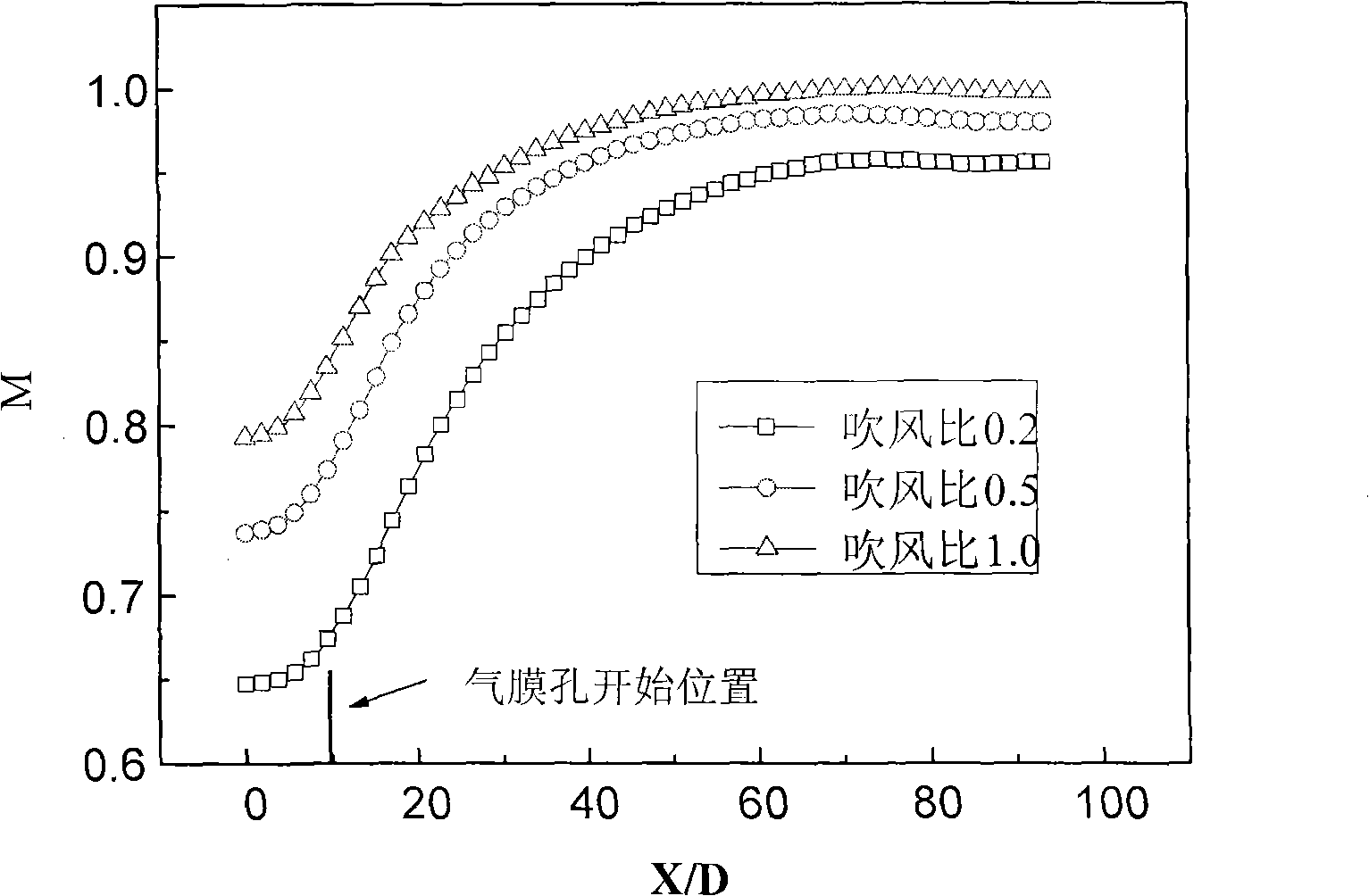
[0028] Adopt a kind of turn-back type compound cooling structure of the present invention to carry out blowing research, research parameter is with reference to the parameter in the typical aero-engine combustor at home and abroad, wherein the inlet temperature and the inlet speed of hot gas stream are respectively T 1 = 1595K and U 1 =80m / s; the inlet temperature of the cooling air flow is T 2 =800K, the import speed is taken as U 2 =8m / s, 20m / s and 40m / s, the blowing ratios of the corresponding cooling airflow at this time are M=0.2, 0.5 and 1.0 respectively.

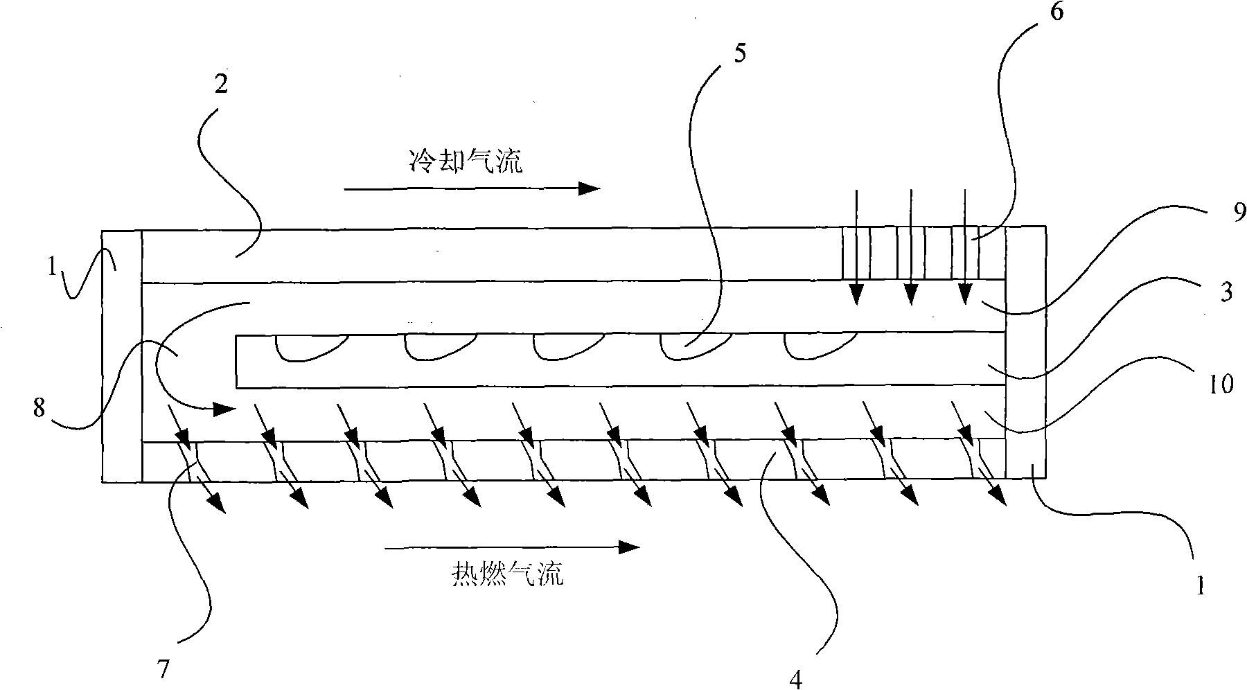
[0029] The results show that: after the cooling air enters the cooling structure from the impact hole 6 of the rear cavity of the outer wall 2 in the form of impact jet flow, it first impacts and cools the rear section of the middle wall 3, and then flows forward and reverse to perform convective heat exchange. The small cell pit 5 enhances the heat exchange. When the cooling air flows to the front end of the upper ...


PUM


Abstract

The invention discloses a reentry type compound cooling structure which comprises an external wall, a middle wall, an internal wall and end walls. The back segment of the external wall is provided with an impact opening; a cooling air slot with certain interval is formed between the middle wall and the front end wall; the internal wall is a cooling structure of a multi-inclined-hole wall, and cooling air flows in a reentry way among the walls of three layers. An impact flow mode is adopted for cooling air. The air flows from back to front in an upper cooling channel composed of the external wall and the middle wall. The heat exchange efficiency of the front segment of the middle wall can be effectively improved by the function of bytyl cellular pits on the middle wall. The air enters a lower cooling channel from the cooling air slot, flows in the reentry way and flows out of the internal wall from a shrinkable and expandable air film hole, and the air film protection is formed at the hot lateral of the internal wall. The shrinking air intake of the shrinkable and expandable air film hole can effectively improve the convective heat transfer of the internal wall of the shrinkable and expandable air film hole, and the expanding gassing can lower the penetration capability of jet flows, strengthen the cover effect of the air film on the hot lateral of the internal wall and effectively protect flame tubes. The cooling structure has the advantages of simple structure, convenient manufacturing and convenient popularization and application.

Description

technical field [0001] The invention relates to the field of enhanced heat transfer and heat protection, in particular to a fold-back composite cooling structure. Background technique [0002] Aviation gas turbine engines are the main power of modern aircraft and helicopters, providing propulsion for aircraft and lift for helicopters. The combustion chamber is an important part of the gas turbine, its combustion characteristics and high temperature thermal protection efficiency directly affect the work and performance of the engine. With the continuous improvement of aero-engine performance, the design of combustion chamber components will develop in the direction of high-temperature rise and high-heat-capacity combustion. Therefore, the research on the cooling of the flame tube has become more important. Generally speaking, the solutions to this problem mainly include: Two: one is to increase the allowable working temperature of the materials used to make the combustion ch...

Claims


Application Information

Patent Timeline
Patent Type & Authority Applications(China)
IPC IPC(8): F23R3/42
Inventor 李志强田涛
Owner BEIHANG UNIV
Why Eureka
Try Eureka