Defect detecting method using a multiple illumination path system

A technology of defect detection and routing, which is applied in the direction of optical test defect/defect, measurement device, printed circuit making wiring diagram, etc., and can solve problems such as unqualified and unqualified production quality

Inactive Publication Date: 2009-09-09
CAMTEK LTD
View PDF0 Cites 4 Cited by
  • Summary
  • Abstract
  • Description
  • Claims
  • Application Information

AI Technical Summary

Problems solved by technology

[0005] Surface defects are the result of substanda

Method used


Image

  • Defect detecting method using a multiple illumination path system
  • Defect detecting method using a multiple illumination path system
  • Defect detecting method using a multiple illumination path system

Examples


Embodiment Construction

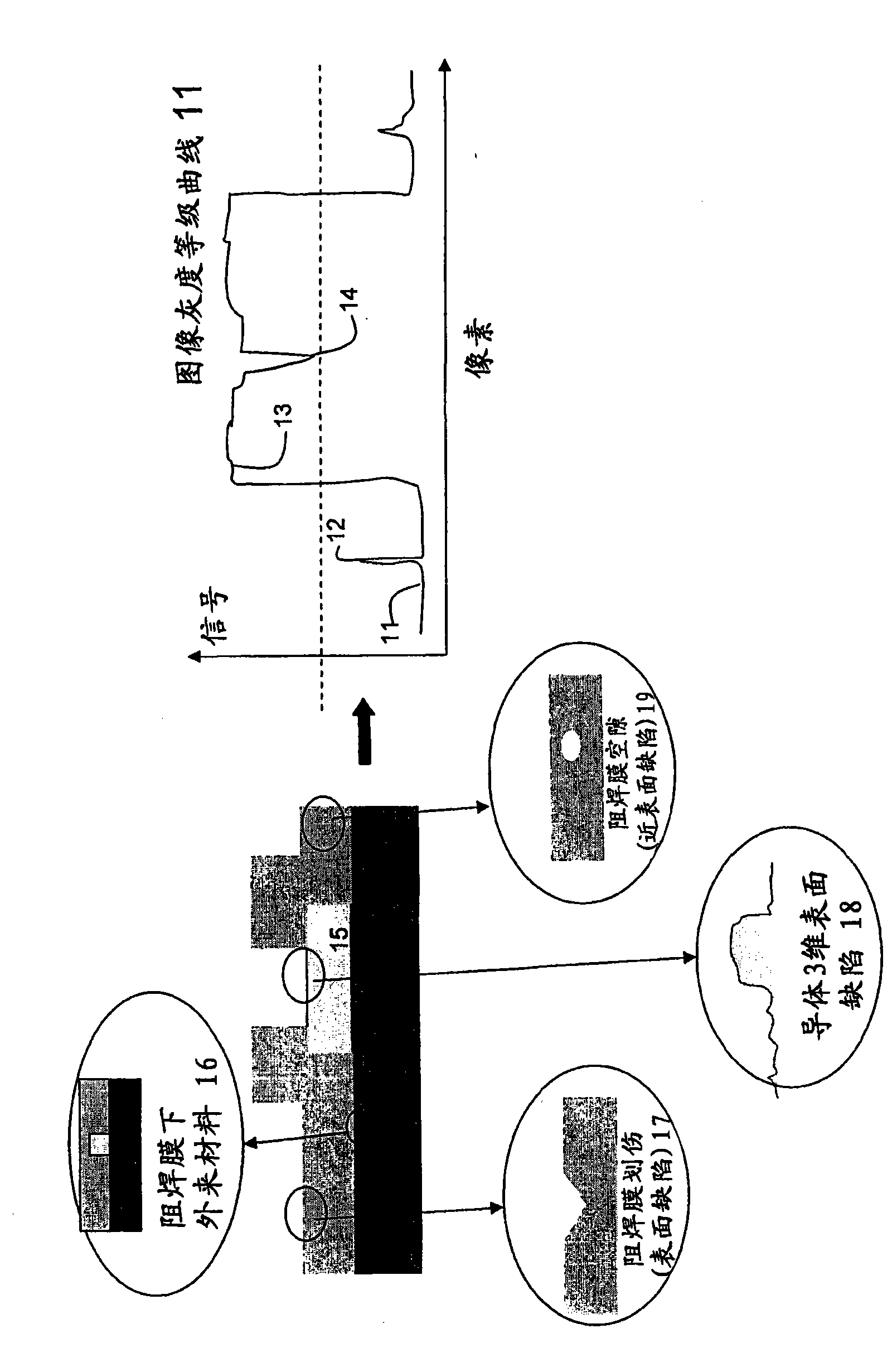
[0031] A multiple lighting path system is provided. It includes multiple illumination paths, processor and imaging paths. The processor is adapted to: (i) control an initial scan of the object; (ii) segment the object into segments based on detection signals obtained during the initial scan; (iii) determine the surface roughness of each segment; and (iv) A selected illumination path to be activated during defect detection of the segment is selected for each segment based on at least one parameter selected from the segment's primary material and the segment's surface roughness level. Multiple illumination paths are used to illuminate objects simultaneously during the initial scan. During a defect detection scan of the object, the selected illumination path illuminates the segment associated with the selected illumination path. The imaging path is adapted to generate a detection signal indicative of a defect in response to said illumination.

[0032] Advantageously, the proce...


PUM


Abstract

The invention provides an efficient method and a system for detection of defect for which need grows more and more. In the multiple illumination path system for detection of defect, a plurality of illumination paths irradiate an object simultaneously during the initial scanning of the object to segment the object to a segment in respons to a detected signal acquired during initial scanning, while during scanning for detection of defect of the segment an illumination path is selected to be active phase for each segment in respons to at least a parameter selected from the main material of the segment and surface roughness level of the segment, each segment of the object is illuminated by only the illumination path selected for the object, and a detected signal is generated indicating defect in respons to the illumination step concerned.

Description

[0001] related application [0002] This application claims priority to US Provisional Patent 60 / 941,672, filed June 3, 2007. technical field [0003] The present invention relates to automated optical inspection systems. Background technique [0004] At the end of the line, prior to packaging and shipment, polished HDI (high-strength interconnect) substrates are visually inspected for surface defects and / or integrity damage. The results of this visual inspection will classify them as pass or fail according to quality control criteria. [0005] Surface defects are the result of substandard production quality and / or substandard operations. Here, the overall quality is related to all surface types involved, ie metal surfaces like gold-plated interconnect pads and solder mask on laminate base material. Each type of such surface is affected by a specific type of defect as a product of its raw material and manufacturing process. [0006] From an optical point of view, each ma...

Claims


Application Information

Patent Timeline
IPC IPC(8): G01N21/88G01N21/01
CPCG01N21/00G01N21/8806G06T7/70H05K3/0002G01N21/95684G06T2207/30141
Inventor D·沙菲洛夫Y·皮恩哈斯
Owner CAMTEK LTD
Why Eureka
Try Eureka