Control method of constant torque of switched reluctance motor

A switched reluctance motor, constant torque technology, applied in torque/mechanical power control, electrical program control, non-electric variable control and other directions, can solve problems such as large torque ripple, achieve small torque ripple, improve The effect of performance, method is simple

Inactive Publication Date: 2009-09-09
HARBIN INST OF TECH
View PDF0 Cites 12 Cited by
  • Summary
  • Abstract
  • Description
  • Claims
  • Application Information

AI Technical Summary

Problems solved by technology

[0003] The purpose of the present invention is to solve the problem of large torque ripple in the method of controlling the torque of the switched reluctance motor using

Method used


Image

  • Control method of constant torque of switched reluctance motor
  • Control method of constant torque of switched reluctance motor
  • Control method of constant torque of switched reluctance motor

Examples


specific Embodiment approach 1

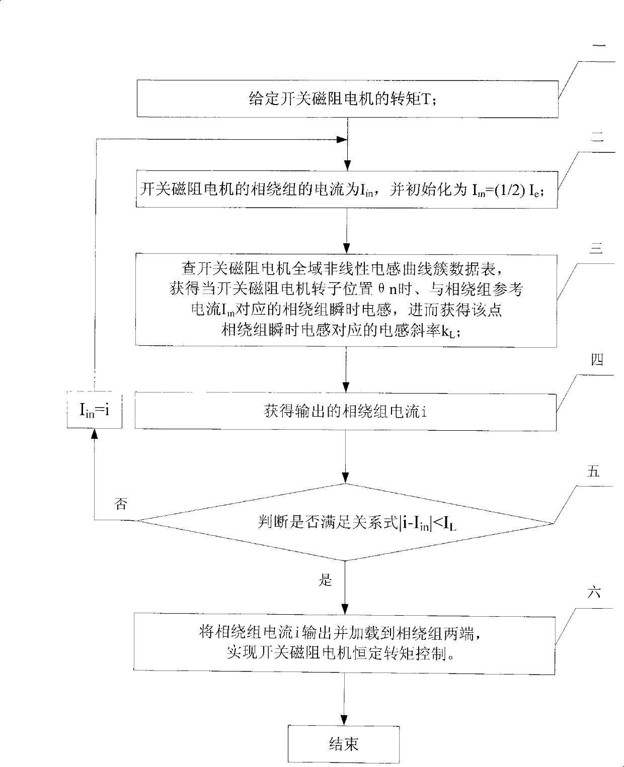
[0016] Specific implementation mode one: the following combination figure 1 , Figure 5 and Figure 6 Describe this embodiment, the method of this embodiment includes the following steps:

[0017] Step 1, given the torque T of the switched reluctance motor;

[0018] Step 2, the reference current of the phase winding of the switched reluctance motor is I in , and initialized to I in = 1 2 I e , where I e is the rated current of the phase winding;

[0019] Step 3: Check the data table of the global nonlinear inductance curve cluster of the switched reluctance motor to obtain the rotor position θ of the current switched reluctance motor n , and the phase winding reference current I in The corresponding instantaneous inductance of the phase winding, and then obtain the inductance slope k corresponding to the instantaneous inductance of the ph...

specific Embodiment approach 2

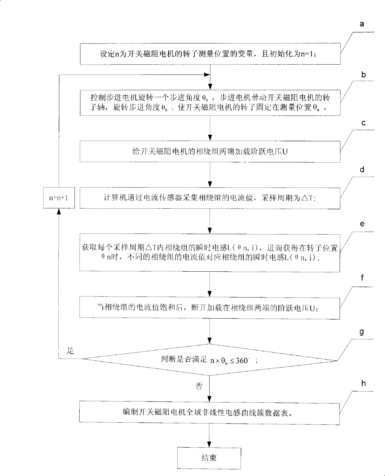
[0042] Specific implementation mode two: the following combination Figure 2 to Figure 5 Describe this embodiment. The difference between this embodiment and Embodiment 1 is that the method for obtaining the global nonlinear inductance curve cluster data table of the switched reluctance motor described in step 3 is as follows:

[0043] Step a, setting n as the variable of the rotor measurement position of the switched reluctance motor, and initializing it as n=1;

[0044] Step b. Control the stepper motor to rotate a step angle θ b , the stepper motor drives the rotor shaft of the switched reluctance motor, and rotates the step angle θ b , so that the rotor of the switched reluctance motor is fixed at the measurement position θ n , 0≤θ n ≤360°;

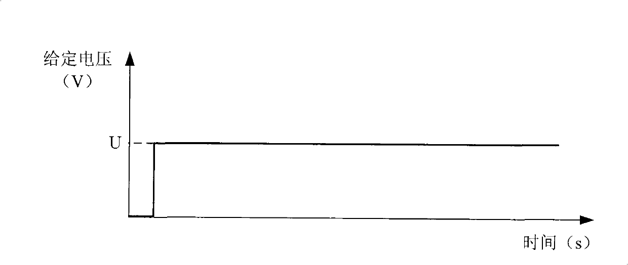
[0045] Step c, applying a step voltage U to both ends of the phase winding of the switched reluctance motor;

[0046] Step d, the computer collects the current value of the phase winding through the current sensor, and the sampli...

specific Embodiment approach 3

[0074] Specific embodiment three: the difference between this embodiment and embodiment two is that the step voltage U=1.2I described in step c e R, others are the same as those in Embodiment 2.

[0075] The voltage value loaded on both ends of the phase winding is set in such a way that the motor will not be burned.


PUM


Abstract

A control method for constant torque of a switched reluctance motor is disclosed, belonging to the field of motor test. The inventive aims at solving the problem that torque pulsation is large when a conventional speed and current double closed-loop control manner is used to control the torque of the switched reluctance motor. The inventive method comprises the steps that: in order to ensure that the switched reluctance motor outputs constantly in accordance with the set torque, a reference current is given at first, a transient inductance corresponding to the reference current is then obtained by inquiring an universe nonlinear inductance curve family data sheet of the switched reluctance motor, an inductance slope corresponding to the transient inductance is further obtained, an output phase winding current is calculated in accordance with the formula i=square root (2T/K<L>), and whether the difference value between the phase winding current and the reference current is in a permissible error range is judged, if not, the phase winding current, which is calculated, is assigned to the reference current and is recalculated in accordance with the method, multiple circulations are implemented until the condition is satisfied, and the output phase winding current is loaded at two ends of the phase winding of the switched reluctance motor to realize control of the constant torque of the switched reluctance motor.

Description

technical field [0001] The invention relates to a constant torque control method of a switched reluctance motor, which belongs to the field of motor testing. Background technique [0002] Due to the advantages of simple structure, convenient control, high reliability and low cost, switched reluctance motor has been valued and recognized by all walks of life. However, the switched reluctance motor also has the disadvantages of large torque ripple and high noise, which limits the application of the switched reluctance motor to a certain extent. important direction. The traditional switched reluctance motor speed control system basically adopts the control mode of speed closed loop and current double closed loop, so that the speed of the switched reluctance motor has a certain stability, but the switched reluctance motor is a kind of motor with high magnetic saturation, and its parameters is non-linear. Especially the inductance parameters of the motor. The inductance of the...

Claims


Application Information

Patent Timeline
IPC IPC(8): G05D17/02G05B19/04
Inventor 吴红星赵哲周寿明嵇恒侯云鹏
Owner HARBIN INST OF TECH
Why Eureka
Try Eureka