Bobbin brake for a winding apparatus of a textile machine which produces crosswound bobbins

A technology of cross-winding and winding device, applied in the direction of brake type, brake components, brake disc, etc., can solve the problems of long braking time, shortened service life of bobbin brakes, large wear of bobbin brakes, etc., and is not easy to wear. , the effect of long service life and high braking torque

Inactive Publication Date: 2009-09-09
SAURER GERMANY GMBH & CO KG
View PDF1 Cites 5 Cited by
  • Summary
  • Abstract
  • Description
  • Claims
  • Application Information

AI Technical Summary

Problems solved by technology

However, such bobbin brakes encounter limitations in modern automatic cross-winders operating at extremely high winding speeds
In other words, the bobbins produced at the stations of modern automatic crosswinders not only rotate at high rotational speeds, but the crosswinders themselves become larger over time and thus significantly heavier, which results in significantly larger of the stress acting on the bobbin brake
High stress not only leads to longer braking times (which negatively affects the overall efficiency of the textile machine) but also greater wear of the package brake (which reduces the service life of the package brake)

Method used


Image

  • Bobbin brake for a winding apparatus of a textile machine which produces crosswound bobbins
  • Bobbin brake for a winding apparatus of a textile machine which produces crosswound bobbins
  • Bobbin brake for a winding apparatus of a textile machine which produces crosswound bobbins

Examples


Embodiment Construction

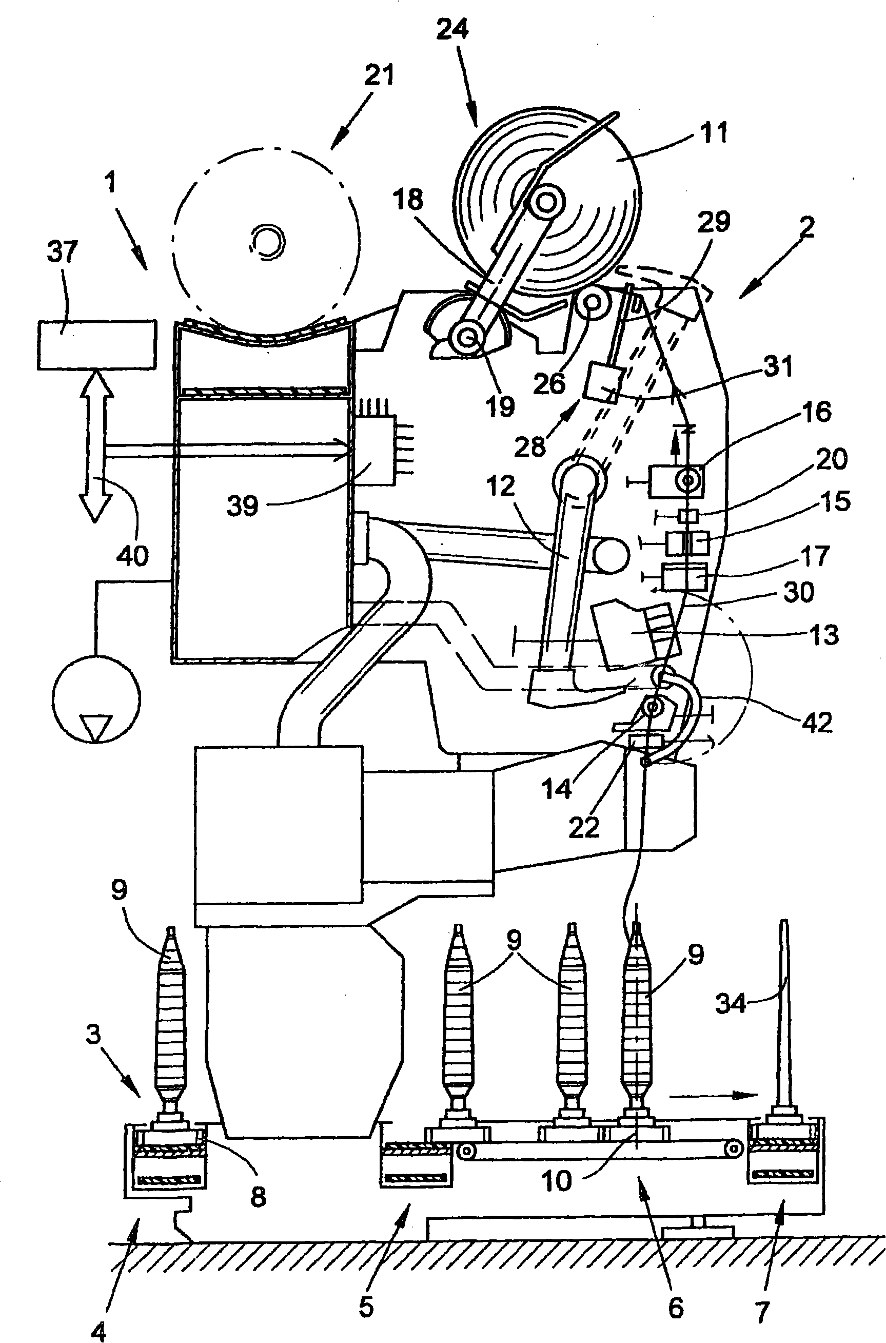
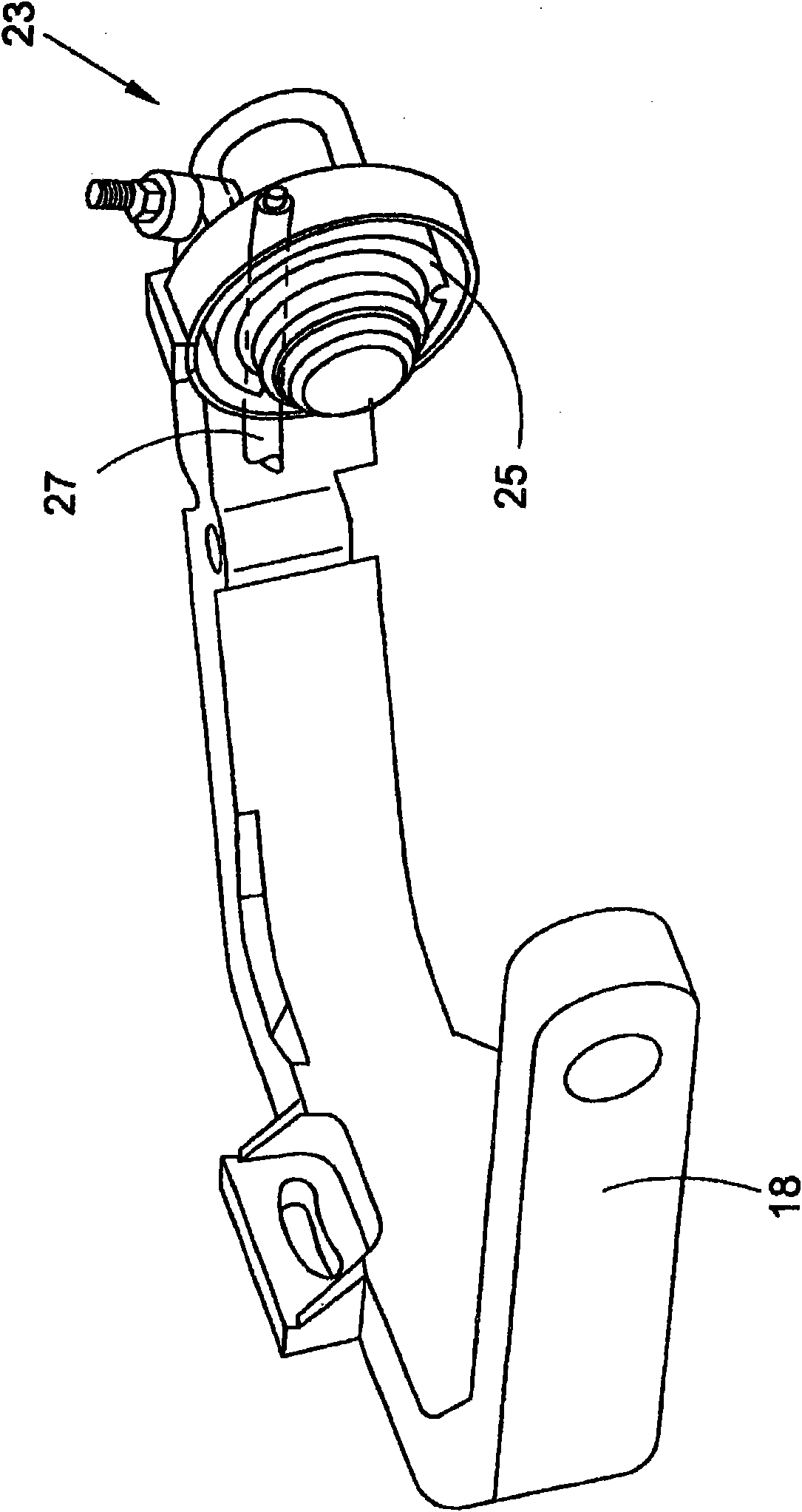
[0018] figure 1 A textile machine for producing cross-winding bobbins (in this example an automatic cross-winding machine), generally designated by reference numeral 1 , is schematically shown in side view. Such automatic cross-winders usually have a plurality of similar stations 2 between their not shown end frames, which in the present case are so-called winders. As is known and therefore not explained in detail, at these winding stations 2 , textile bobbins 9 , produced for example on ring spinning machines, are rewound into bulky cross-winding bobbins 11 . After the cross-winding bobbin 11 has been produced, it is handed over to the cross-winding bobbin transport 21 along the machine length by means of an automatically operating service unit (not shown), preferably a cross-winding bobbin changer, and transported to The bobbin loading station set at the end of the machine, etc.

[0019] Such an automatic crosswinder 1 usually also has a logistics device in the form of a b...


PUM


Abstract

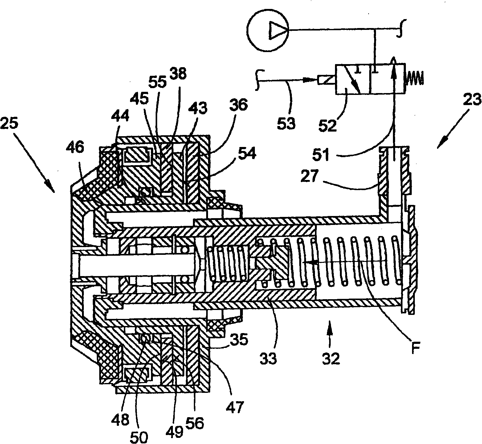
The invention relates to a bobbin brake (23) for a winding apparatus (24) of a textile machine (1) which produces crosswound bobbins having a rotatably mounted empty-bobbin receiving plate (25) which is provided with a rear-side brake face (49), an axially displaceably mounted brake housing (35) which is equipped with a brake lining (36), and a device (32) for moving the brake housing (35) into a braking position, wherein the brake housing (35) is moved towards the empty-bobbin receiving plate (25). There is provision according to the invention for the brake housing (35) to have, in addition to the brake lining (36) which is arranged fixedly on the brake housing (35), a brake ring (38) which is connected fixedly in terms of rotation to the brake housing (35) but is mounted such that it can be displaced axially with regard to the brake housing (35), and for a sleeve-like brake disc (43) to be installed between the brake lining (36) and the brake ring (38), which sleeve-like brake disc (43) is arranged fixedly in terms of rotation but axially displaceably in a rotatably mounted receiving housing (45) of the empty-bobbin receiving plate (25), which receiving housing (45) has a brake face (49) which is arranged on the end side.

Description

technical field [0001] The invention relates to a bobbin brake for a winding device of a textile machine for producing cross-wound bobbins according to the preamble to the first aspect. Background technique [0002] Such bobbin brakes have been known for a long time in association with so-called automatic crosswinders, and have been described in more detail, for example, in page 1.3.8 of the Schlafhorst company's manual "AUTOCONER System 238" or in DE 196 50 932 A1 The bobbin brake is described. [0003] These known bobbin brakes are present at each station of the automatic crosswinding machine and are respectively integrated in the creel holder which rotatably holds the crosswinding bobbin or its bobbins during the winding operation . These cartridge brakes each have a pneumatic brake cylinder to which compressed air can be applied in a predetermined manner through a solenoid valve connected in the pneumatic line and connected to the workstation computer. In addition, th...

Claims


Application Information

Patent Timeline
Patent Type & Authority Applications(China)
IPC IPC(8): B65H63/036B65H59/38F16D65/12
CPCB65H63/0366B65H2701/31F16D2121/02B65H59/381F16D65/186B65H54/74
Inventor 弗兰克·勒文夫斯
Owner SAURER GERMANY GMBH & CO KG
Why Eureka
Try Eureka