
Pressure cylinder with composite piston rod and method for preparing a composite piston rod

A composite material fiber and pressure cylinder technology, applied in the field of pressure cylinders, can solve the problems of weight reduction, high cost price, unsatisfactory, etc., and achieve the effect of additional reliability, fast and easy manufacturing, and high pressure load

Inactive Publication Date: 2009-09-09
ZUMRO
View PDF1 Cites 12 Cited by
  • Summary
  • Abstract
  • Description
  • Claims
  • Application Information

AI Technical Summary

Problems solved by technology

[0005] Although significant weight savings can be achieved with this known pressure cylinder, it is still not ideal
The structure of alternating straight fibers in the layers of core material and fibers wound around them results in less compaction of the fibers
Especially in the case of compressive strength, it has been found in practice that a comparatively large amount of material is required for the piston rod to ensure a defined loadability, which leads to a high overall weight and volume and, of course, a high cost price

Method used


Image

  • Pressure cylinder with composite piston rod and method for preparing a composite piston rod
  • Pressure cylinder with composite piston rod and method for preparing a composite piston rod
  • Pressure cylinder with composite piston rod and method for preparing a composite piston rod

Examples


Embodiment Construction

[0029] The drawings are only schematic and not drawn to scale. Some dimensions may be particularly exaggerated to larger or smaller extents for clarity. Corresponding parts are provided with the same reference symbols as far as possible in the figures.

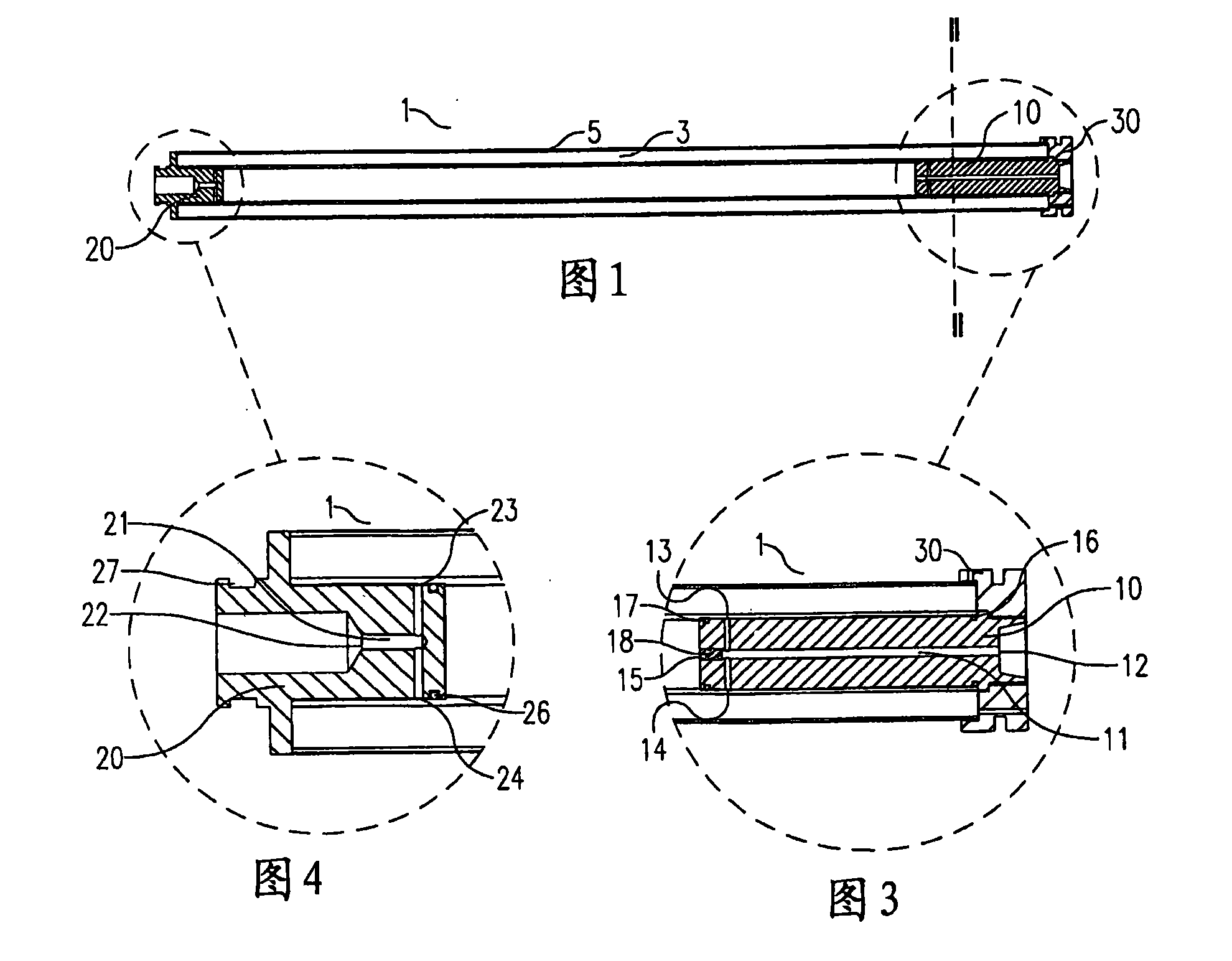
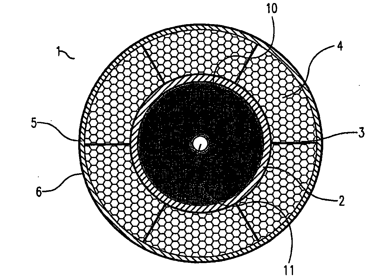
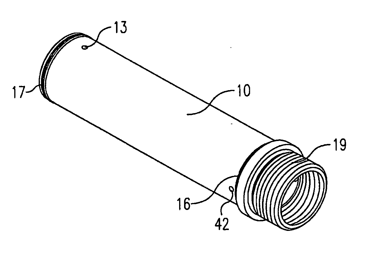
[0030] An exemplary embodiment of a piston rod used in a pressure cylinder according to the invention is shown in longitudinal section in figure 1 . The hollow piston rod 1 comprises a layer of core material 3 under a peripheral sheath 5 and is provided with an insert 10 at the proximal end and a closure 20 at the distal end. The distal end of the anodized high grade aluminum insert 10 is matingly bonded to the piston rod, while the proximal end of the insert 10 is screwed to the piston 30 by means of threads (not shown). The distal end of the insert 10 may also comprise a thread and thus be connected to the piston rod by means of a threaded connection.

[0031] figure 2 , 3 , 4 respectively show along the figure 1 The...


PUM


Abstract

A pressure cylinder comprises a cylinder housing with a cylinder space in which a fitting piston is axially movable. A piston rod (1) of a composite material extends from the piston. The piston rod (1) comprises a layer of core material under a surrounding outer jacket (5). The layer of core material (3) is constructed from composite material fibres oriented parallel to a longitudinal axis of thepiston rod and straightened, and the outer jacket (5) is constructed from composite material fibres wound at an angle relative to the longitudinal axis. Thus provided is a pressure cylinder with a piston rod (1) of relatively light weight, which can withstand a relatively high pressure load. Less composite material is hereby required for the piston rod (1) while the strength remains the same.

Description

technical field [0001] The invention relates to a pressure cylinder comprising a cylinder space delimited by a cylinder housing in which there is an axially displaceable cooperating piston, wherein a piston rod at least substantially made of fiber composite material extends from the piston, the piston The rod essentially comprises a layer of core material under a peripheral jacket. Background technique [0002] Pressure cylinders come in many shapes and sizes and are usually tailored to a specific application. Metal, in particular stainless steel, is usually used here as the material for the cylinder housing, piston rod and piston, because these materials are robust, durable and relatively easy to process, and the raw materials are more affordable. However, metal as the basic material of the pressure cylinder also has disadvantages, especially its relatively high specific gravity. The finished pressure cylinder therefore has a considerable overall weight, which is a disadv...

Claims


Application Information

Patent Timeline
Patent Type & Authority Applications(China)
IPC IPC(8): F15B15/14
CPCF15B2215/305F15B15/1457Y10T74/2142
Inventor F·巴斯A·J·马尔斯乔克
Owner ZUMRO
Learn More