Thermal displacement correcting method of a machine tool and a termal displace ment correcting device

A thermal displacement and machine tool technology, applied in feeding devices, automatic control devices, computer control, etc., can solve problems such as inability to make accurate predictions, and achieve high-precision results

Active Publication Date: 2009-09-16
BROTHER KOGYO KK
View PDF0 Cites 22 Cited by
  • Summary
  • Abstract
  • Description
  • Claims
  • Application Information

AI Technical Summary

Problems solved by technology

Therefore, the above method cannot make accurate predictions

Method used


Image

  • Thermal displacement correcting method of a machine tool and a termal displace ment correcting device
  • Thermal displacement correcting method of a machine tool and a termal displace ment correcting device
  • Thermal displacement correcting method of a machine tool and a termal displace ment correcting device

Examples


Embodiment 1

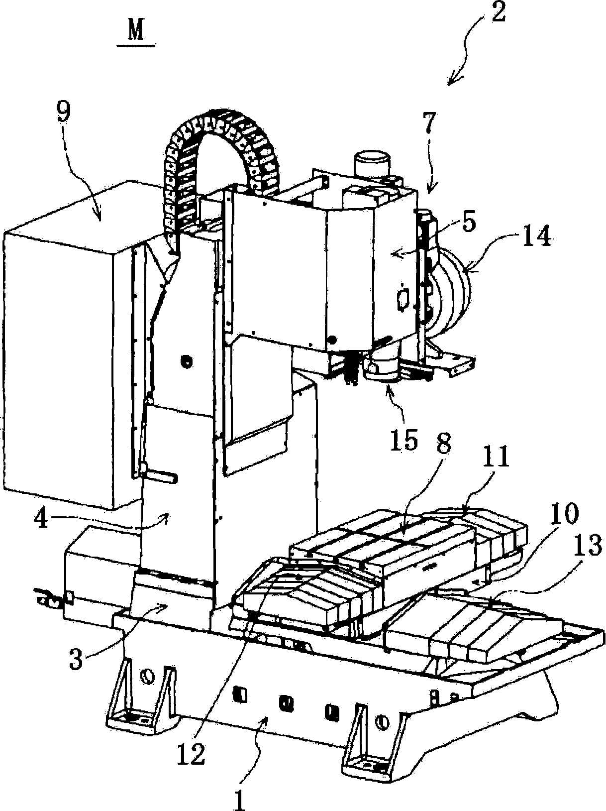
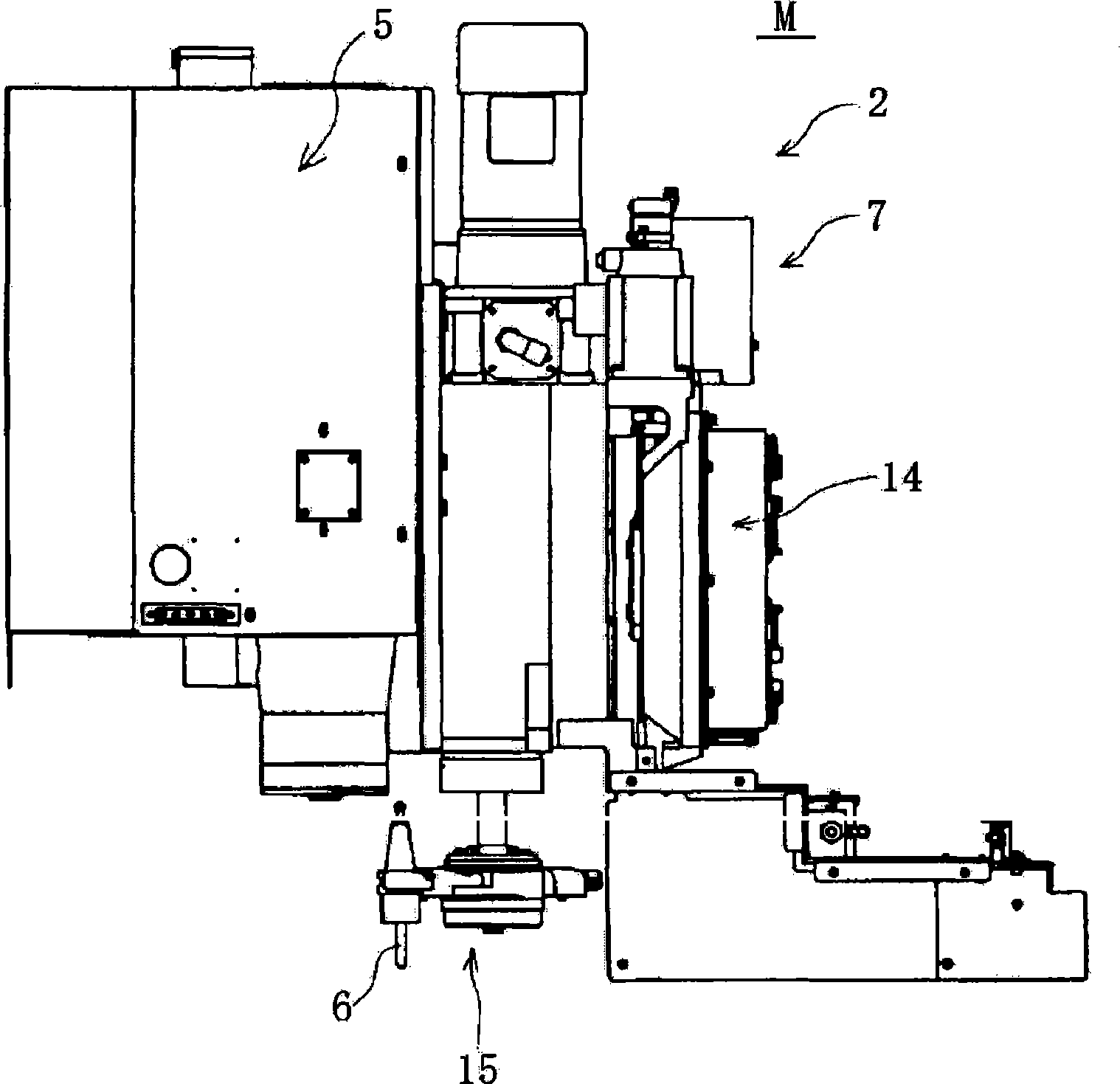
[0036] refer to Figure 1 ~ Figure 4 The structure of the machining center M (machine tool) will be described. figure 1 The machining center M shown is a machine tool capable of performing desired machining (such as "milling", "drilling", and "cutting") on a workpiece by relatively moving the workpiece and the tool. The machining center M mainly includes: a base 1 made of cast iron, a machine tool body 2 arranged on the upper part of the base 1 , and a protective baffle (not shown) fixed on the upper part of the base 1 . The machine tool body 2 performs cutting processing of workpieces. The protective shutter is a box-shaped cover that covers the machine tool body 2 and the upper part of the base 1 .

[0037] The base 1 is a substantially cuboid cast product long in the Y-axis direction. Height-adjustable feet are respectively arranged in the four corners of the lower part of the base 1 .

[0038] Next, the machine tool body 2 will be described. Such as figure 1 As sho...

Embodiment 2

[0130] Other embodiments will be described below. The difference from Example 1 above is that the temperature rise of the servo motor is calculated using a temperature sensor attached to the servo motor and a room temperature sensor for measuring room temperature instead of using the current and rotation speed.

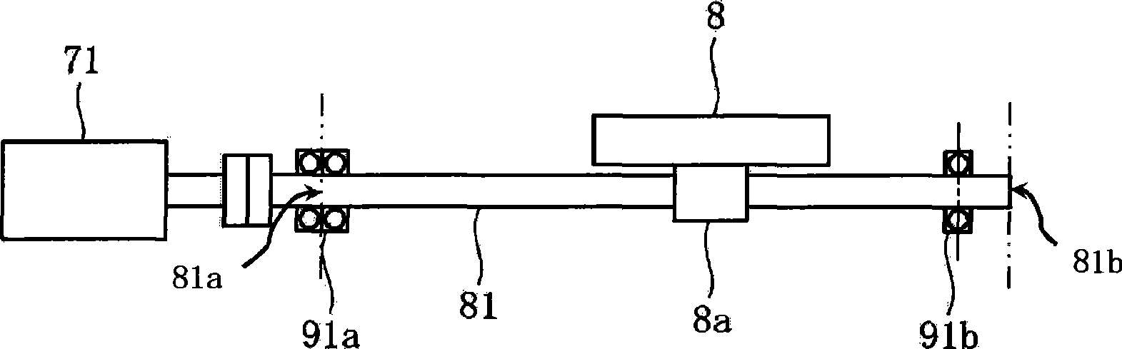
[0131] The temperature Θ of the servo motor body detected by a temperature sensor (not shown) separately provided on the X-axis motor 71 MO , and the Θatm detected by the room temperature sensor (not shown) installed on the machining center M to detect the temperature of the outside air is sent to the CPU51. The CPU 51 uses the following equation to obtain the temperature rise Θ of the servo motor body.

[0132] Θ = Θ MO —Θatm

[0133] Heating value Q of front bearing part F It is formed by the input heat generated by the temperature rise of the servo motor. Therefore, the CPU 51 uses the following formula to obtain the heat generation value Q of the front bearing ...


PUM


Abstract

The present invention provides a thermal displacement correcting method of a machine tool and a thermal displacement correcting device, which is used to correct error caused by thermal displacement of a ball screw mechanism generated in operation of a machine tool. A first heat productivity computing division calculates a first heat productivity generated by a nut on a screw axis according to a rotary speed detected by a speed detector; a second heat productivity computing division calculates a second heat productivity generated by a servo motor on a screw axis according to a temperature increase detected by a temperature detecting division. A temperature distribution computing division calculates the temperature distribution that separated into a plurality of zones in length direction of the screw axis. A thermal displacement quantity computing division calculates thermal displacement quantity of each zone according to temperature distribution calculated by the temperature distribution computing division. A correction computing division calculates a correction of machining data for nut feed calculation according to the thermal displacement quantity calculated by the thermal displacement quantity computing division.

Description

technical field [0001] The invention relates to a thermal displacement correction method and a thermal displacement correction device of a machine tool. More specifically, the present invention relates to a method and an apparatus for correcting errors caused by thermal displacement of a ball screw mechanism during operation of a machine tool. Background technique [0002] Ball screw mechanisms are becoming popular as positioning mechanisms for machine tools. The temperature of the ball screw mechanism rises due to the frictional resistance between the screw shaft and the nut, the frictional resistance between the screw shaft and each part of the bearing, and the heat generated by the servo motor. The ball screw mechanism generates thermal displacement (elongation) due to the above-mentioned temperature rise. The current control mode of CNC machine tools is generally semi-closed loop. In a semi-closed-loop CNC machine tool, the thermal displacement of the screw shaft is d...

Claims


Application Information

Patent Timeline
Patent Type & Authority Applications(China)
IPC IPC(8): B23Q15/18B23Q17/00G05B19/404
CPCB23Q11/0003G05B2219/49209G05B19/404B23Q17/0985G05B19/414
Inventor 小林治夫
Owner BROTHER KOGYO KK
Why Eureka
Try Eureka