Three-dimensional composite flexible joint

A flexible joint and composite technology, applied in the direction of manipulators, manufacturing tools, joints, etc., can solve the problems of miniaturization difficulties, small stroke and large volume of pneumatic bellows, and achieve good market prospects, stable movements and good adaptability Effect

Inactive Publication Date: 2009-09-16
BEIHUA UNIV
View PDF0 Cites 47 Cited by
  • Summary
  • Abstract
  • Description
  • Claims
  • Application Information

AI Technical Summary

Problems solved by technology

The flexible joints driven by micro-motors and cylinders are basically mature and widely used, but they are large in size and the degree of joint flexibility is limited by some factors; artificial muscles are nonlinear components, the law of power output is difficult to grasp, and the control algorithm is relatively complicated; The pneumatic bellows has a small stroke and a large volume, and is mainly used for micro-motion joints.
The above driving devices must be used in conjunction with the mechanical structure during the application process, which is bulky and difficult to miniaturize
The motion trajectory of the joint is determined by the mechanical structure, with poor flexibility and limited spatial dimensions
[0004] At present, the existing artificial joints cannot fully meet the special needs in the fields of handling industrial products with large changes in form, underwater bionics, and special robots. It is necessary to continue to develop highly flexible joints.

Method used


Image

  • Three-dimensional composite flexible joint
  • Three-dimensional composite flexible joint
  • Three-dimensional composite flexible joint

Examples


Embodiment Construction

[0014] The present invention will be further described in detail below in conjunction with the accompanying drawings and specific examples.

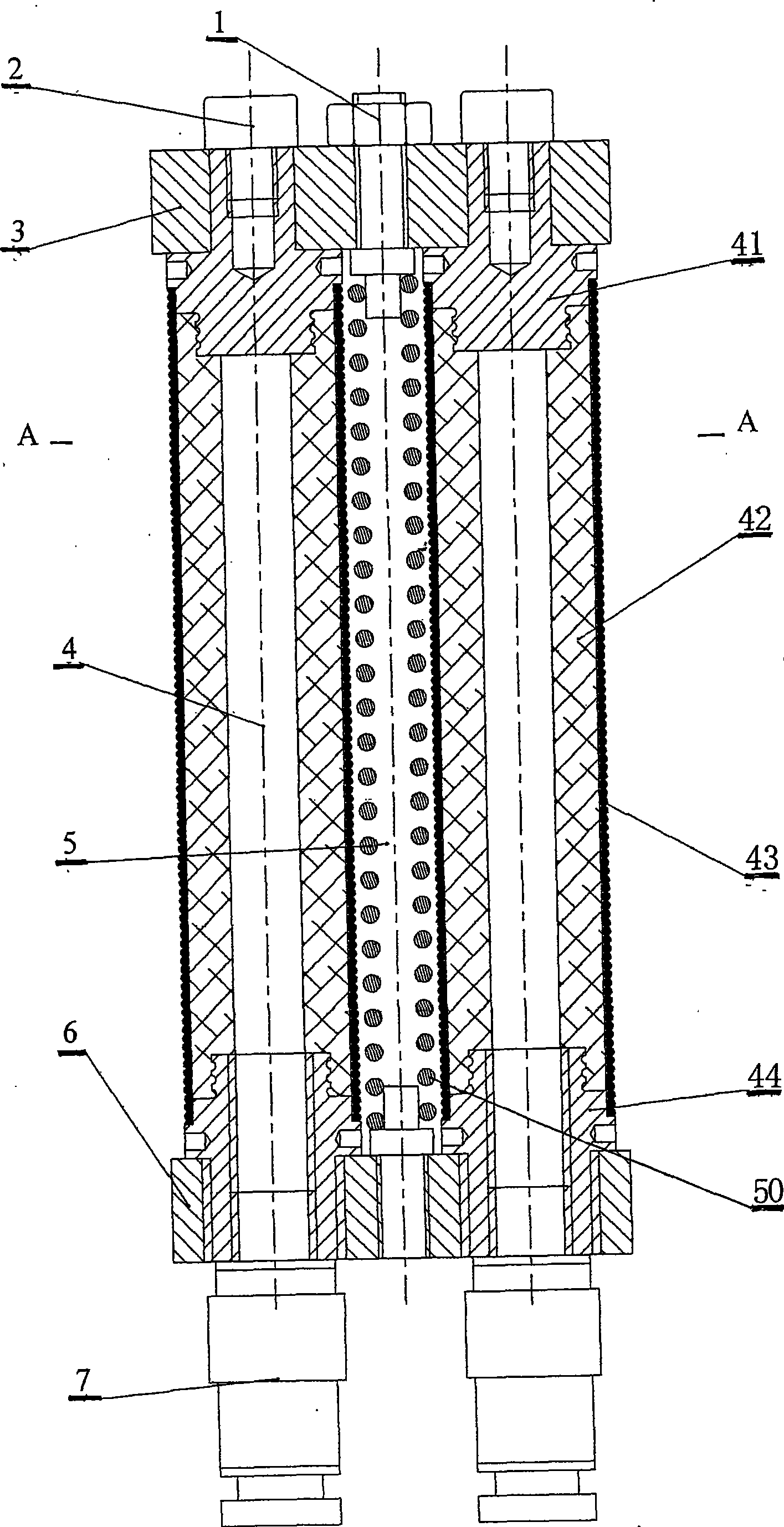
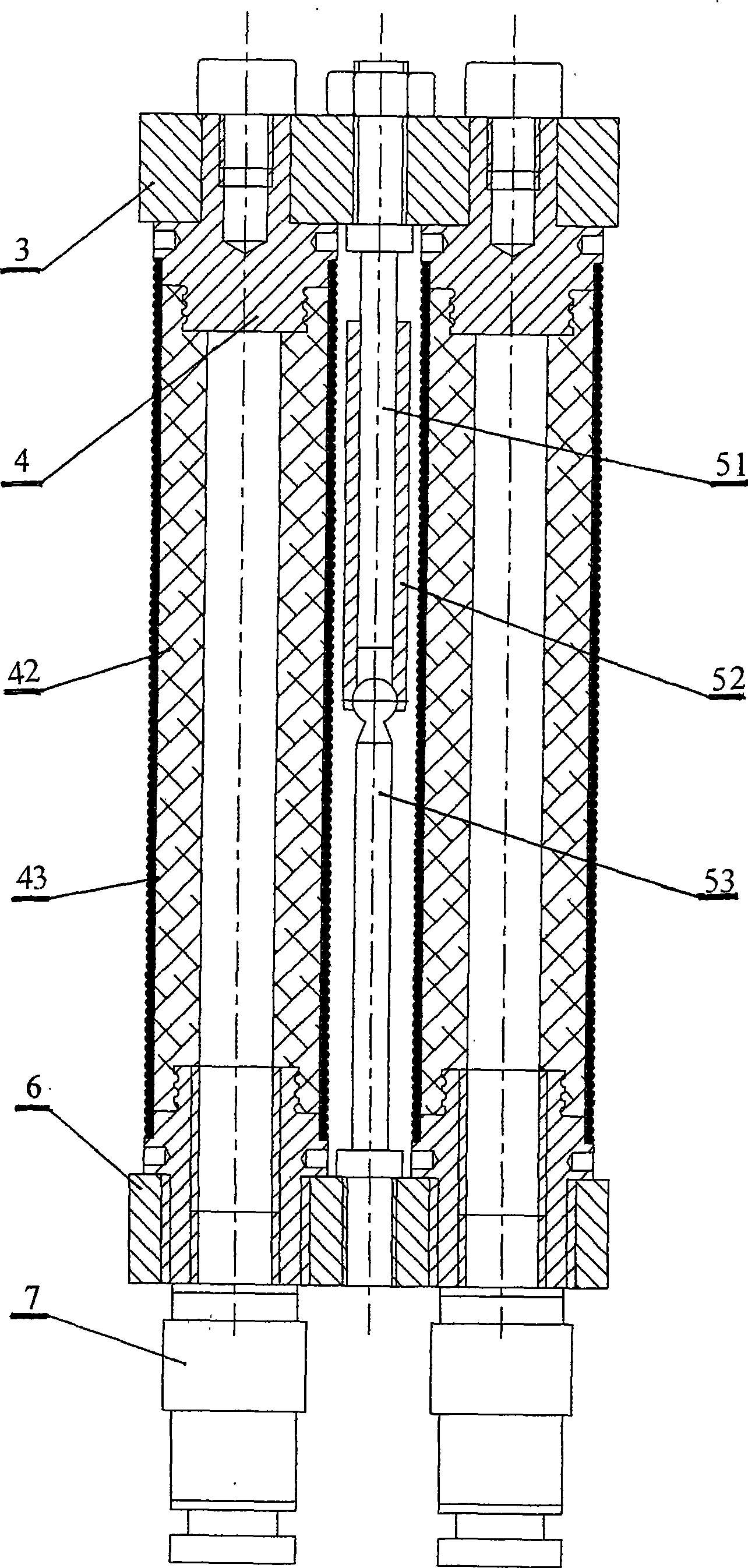
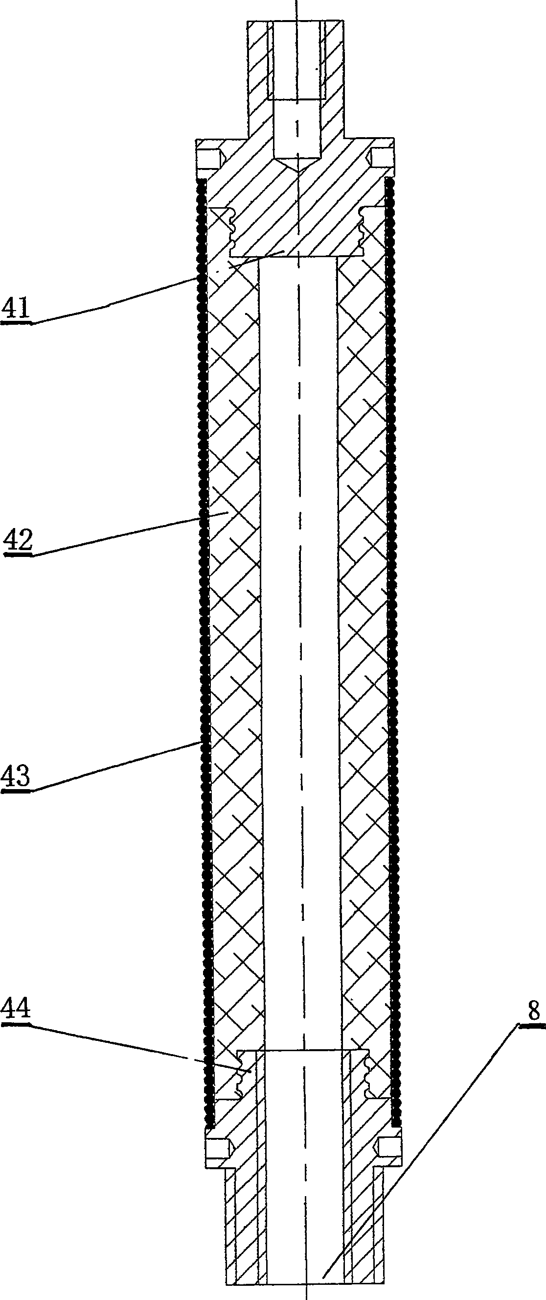
[0015] The present invention is composed of an elongated artificial muscle 4, a central skeleton 5 and joint flanges 3, 6; the skeleton 5 is located on the central axis of the joint, and its two ends are fixedly connected with the joint flanges 3, 6; Rigid spring skeleton or multi-dimensional skeleton; the joint drive is completed by several elongated artificial muscles 4, which are arranged in a ring along the center of the joint, and the two ends of each elongated artificial muscle 4 are connected to the upper and lower joint flanges 3, 6 connections. Flesh and flesh are integrated, and there are decorations on the outside.

[0016] figure 1 It is a schematic diagram of the spring skeleton flexible joint structure composed of four elongated artificial muscles. In the figure, there are nuts 1, screws 2, upper flange 3, elongated artif...


PUM


Abstract

The invention discloses a joint used for a robot limb and relates to a three-dimensional composite flexible joint which is characterized in that several groups of extended artificial muscles are arranged between an upper flange and a lower flange; a framework is arranged in a cavity formed by the several groups of extended artificial muscles; the extended artificial muscle is as follows: a spring is arranged between an upper end cover and a lower end cover, a capsule is arranged in a tubular cavity formed by the spring, and the lower end cover is provided with a fluid inlet; the framework is made of a tubular spring and also can be a component formed by a movable pair and a spherical pair in series; and two ends of the framework are fixed on the upper flange and the lower flange of the joint. The three-dimensional composite flexible joint has the advantages that the three-dimensional composite flexible joint has small size and good flexibility; a drive set of the joint is combined with the joint as a whole; the three-dimensional composite flexible joint can realize axial elongation and curvature of space, can realize the complex action of a bionic artificial joint, act stably and is fit for capturing or conveying objects with irregular shapes; and the three-dimensional composite flexible joint has popularization and application values in the field of bionic and specific robot and has very good market prospect.

Description

technical field [0001] The invention relates to a flexible joint for a robot limb. Background technique [0002] With the development of science and technology, the application of robots has been paid more and more attention by people, and the application of flexible joints in the field of robot technology and bionic technology has become more and more extensive. It plays an important role. Therefore, the research on it at home and abroad has attracted more and more attention, and the results have been fruitful. The main content of the research is the realization of joint drive devices, drive materials and joint flexible structures. Among them, the joint drive is the research focus, and the drive material is the research difficulty. [0003] The flexible joints that have been researched and developed now mainly include several structural forms such as micro-motor drive, cylinder drive, artificial muscle drive, pneumatic bellows drive and electric drive. The flexible joints...

Claims


Application Information

Patent Timeline
Patent Type & Authority Applications(China)
IPC IPC(8): B25J17/00B25J19/00
Inventor 耿德旭张金涛赵云伟张贵兰
Owner BEIHUA UNIV
Why Eureka
Try Eureka