
Method for online separately detecting resistive leakage current of non-voltage reference source

A resistive current and leakage current technology, applied in the measurement of current/voltage, measuring device, RMS measurement, etc., can solve the problems of thermal collapse of arrester, power failure, increase of resistive current component, etc., to achieve enhanced effectiveness and efficiency. Accuracy, the effect of improving reliability

Inactive Publication Date: 2009-09-16
李新育
View PDF0 Cites 15 Cited by
  • Summary
  • Abstract
  • Description
  • Claims
  • Application Information

AI Technical Summary

Problems solved by technology

Under normal conditions, the resistive current component is much smaller than the capacitive current component. If a shielding device is used to eliminate the influence of the outer porcelain sleeve of the arrester, the full current inside the arrester is generally about 700uA, while the resistive current is only about 150uA. When the value of the capacitive current is close to the full current, even if the change of the resistive current is more than doubled, the change of the reading reflected on the monitor is not obvious, so this leakage current monitor cannot effectively reflect the change of the resistive current. Changes
However, the fault of the arrester is often caused by the increase of the resistive current component in the leakage current. Due to the increase of the resistive current, the active component increases, which will lead to the thermal collapse of the arrester after reaching a certain level. If the fault arrester cannot be withdrawn in time operation, it is likely to explode within days or hours, causing widespread power outages

Method used


Image

  • Method for online separately detecting resistive leakage current of non-voltage reference source
  • Method for online separately detecting resistive leakage current of non-voltage reference source

Examples


Embodiment Construction

[0015] The present invention will be further described in detail through specific embodiments below.

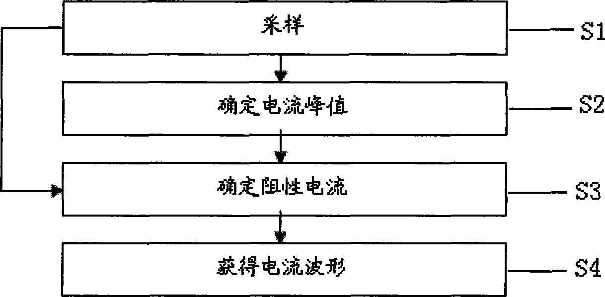
[0016] A method for on-line separation and detection of resistive leakage current without a voltage reference source, comprising the following steps:

[0017] Sampling step S1, sampling a fixed-period surge arrester leakage full-current period signal;

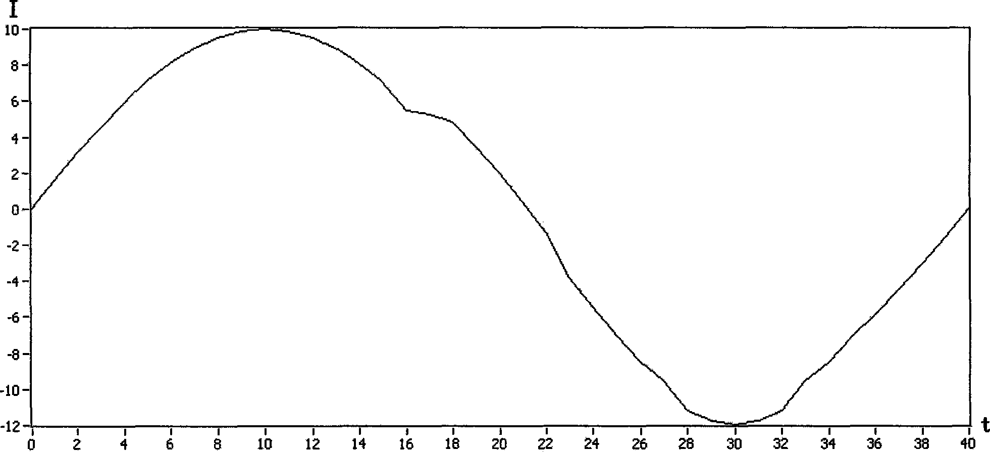
[0018] Determine the current peak value step S2, determine the peak value of the capacitive current according to the leakage full current period signal sampled in the sampling step S1, the current peak value is obtained by finding the first value of the monotonically increasing function in one period of the full wave signal of the leakage full current signal A positive extreme point, and it is realized as the peak value of the capacitive current;

[0019] Determine the resistive current step S3, according to the leakage full current cycle signal sampled in the sampling step S1 and the peak value of the capacitive current dete...


PUM


Abstract

The invention discloses a method for online separately detecting resistive leakage current of a non-voltage reference source, thereby realizing that the resistive current value can be effectively acquired, validity and accuracy of detection of the lightning arrester state can be improved, and the reliability of system operation can be improved. The invention is realized through the following technical proposal that the method for online separately detecting resistive leakage current of the non-voltage reference source comprises the following steps: firstly, sampling a leakage full current periodic signal of the lightning arrester with fixed period; secondly, determining a peak value of capacity current according to the leakage full current periodic signal sampled on the step S1; thirdly, acquiring leakage resistive current through calculating according to the leakage full current periodic signal sampled on the step S1 and the peak value of the capacity current determined on the step S2 of determining the current peak value; and finally, determining a periodical leakage resistive current waveform according to the leakage resistive current acquired by calculation on the step S3 of determining the resistive current.

Description

technical field [0001] The invention relates to a method for separately detecting a resistive leakage current, in particular to a method for on-line separation and detection of a resistive leakage current without a voltage reference source. technical background [0002] Zinc oxide arrester is a kind of protective equipment to protect electrical equipment from overvoltage. Due to the superior nonlinear characteristics and good flow capacity of the zinc oxide arrester, it has been accepted and widely used by users in the power sector. Damage and electrical accidents also occur, especially zinc oxide surge arresters with a voltage level of 110kV and above, once an accident occurs, it will cause huge losses to users. Therefore, on the basis of continuously improving the manufacturing level of arresters and ensuring the quality of arresters, actively carrying out further research on the operation status of arresters will help the safe operation of power equipment. [0003] At p...

Claims


Application Information

Patent Timeline
IPC IPC(8): G01R19/00G01R19/02G01R19/04
Inventor 李新育祝铭董慈航
Owner 李新育
Learn More