Device to coat metallic coating onto wafer

A metal coating and wafer technology, applied in the direction of electrical components, semiconductor/solid-state device manufacturing, circuits, etc., can solve problems such as limiting productivity and achieve high productivity

Inactive Publication Date: 2009-09-16
COLORFUL TC PRINTING MACHINES
View PDF3 Cites 3 Cited by
  • Summary
  • Abstract
  • Description
  • Claims
  • Application Information

AI Technical Summary

Problems solved by technology

This high accuracy limits the speed at which the wafer can move, and thus limits throughput

Method used


Image

  • Device to coat metallic coating onto wafer
  • Device to coat metallic coating onto wafer
  • Device to coat metallic coating onto wafer

Examples


Embodiment Construction

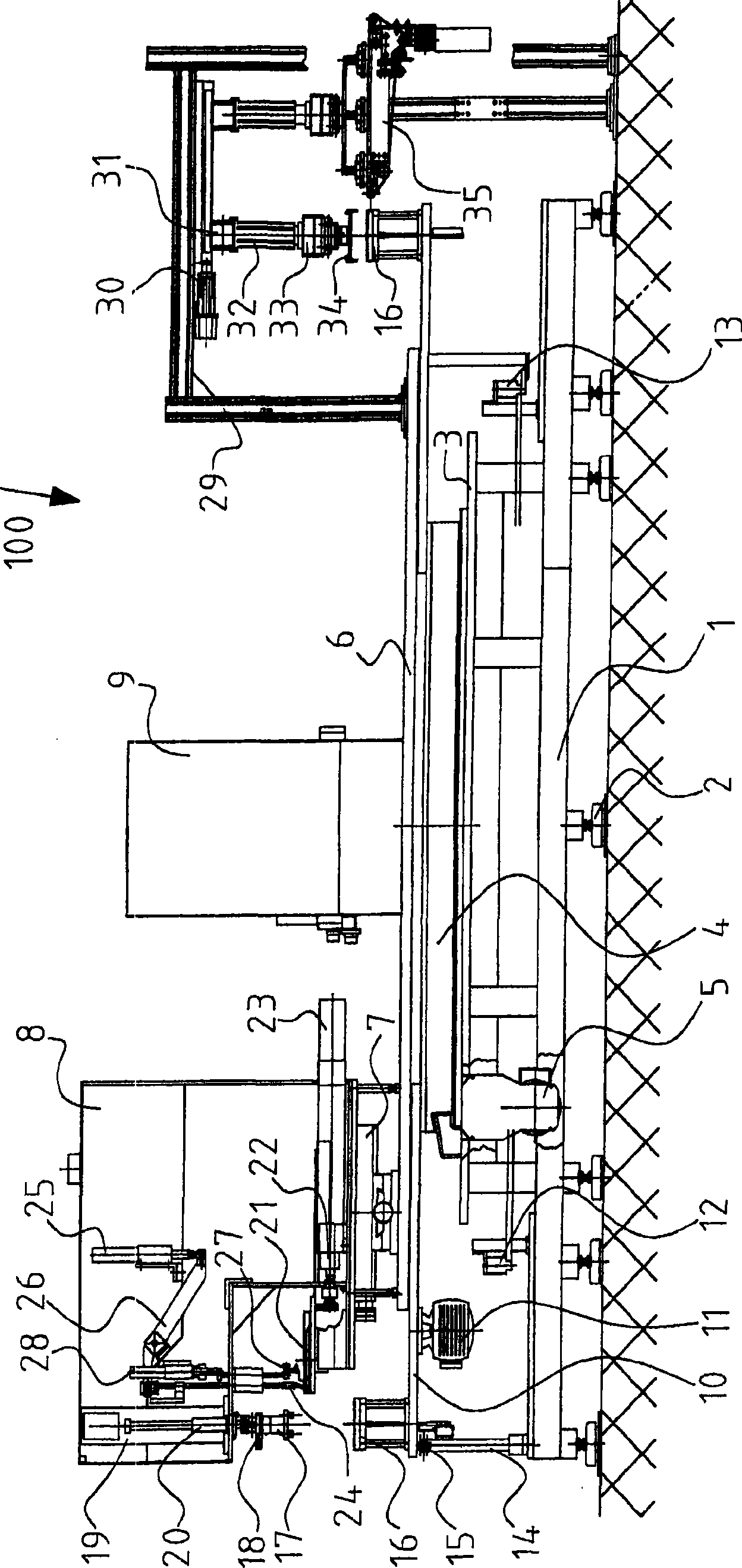
[0024] figure 1 A device 100 for applying a metal coating to wafers, not shown in detail, is shown. The device 100 has a base 1 which is supported on the ground by means of feet 2 . The feet 2 are adjustable so that the base 1 can be oriented horizontally. Arranged on the base 1 is a base plate 3 for a circular switch disk 4 , which can be rotated by means of a drive 5 in predetermined angular increments.

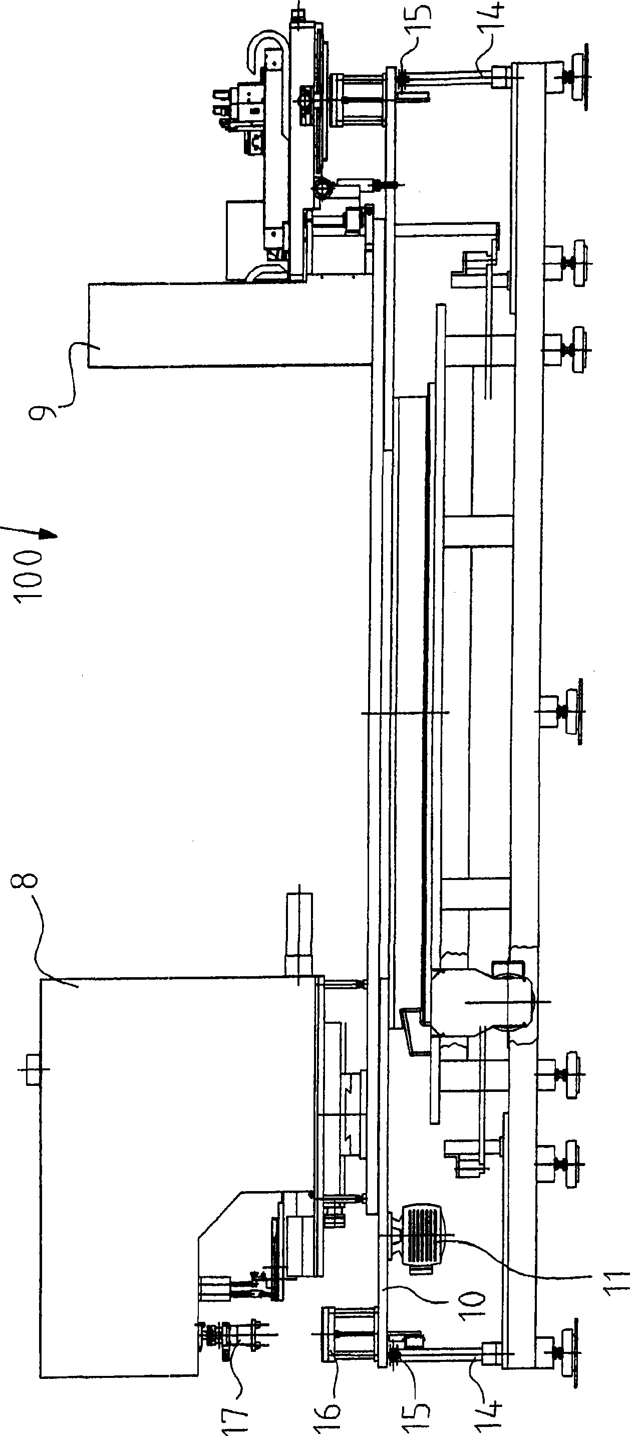
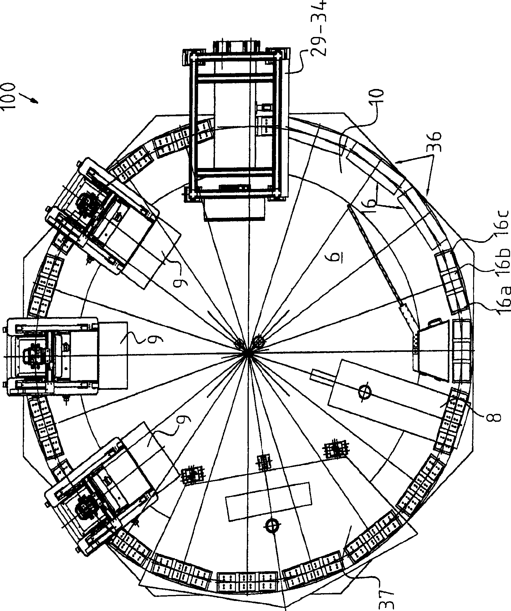
[0025] Furthermore, a base 6 is arranged on the base, on which a pad printing device 8 supported by an Oldham slide 7 is arranged. With the aid of the cross slide 7, the pad printing unit 8 can be positioned with very high precision. In addition, three screen printing devices 9 are arranged on the base 6. figure 1 and 2 Only one of the screen printing devices can be seen in each case. However, from image 3 See the layout of the three screen-printed setups.

[0026] The rotary table 10 is controlled to rotate around the base 6 by the drive device 5 . A plurality of...


PUM


Abstract

The present invention discloses a device (100) that used to coat a metal coating onto a wafer, wherein the device is provided with at least one printing apparatus (8, 9) and at least one work piece plug socket (16). The device is made for improving productivity and therefore is designed as arranging the work piece plug socket (16) on a rotary display stand (10) which could rotate relative to a foundation bed (6) and arranging the printing apparatus (8, 9) on the foundation bed.

Description

technical field [0001] The invention relates to a device for applying a metallic coating to a wafer, which device has at least one printing unit and at least one workpiece socket. Background technique [0002] The rear side of wafers made of silicon or other semiconductor materials must in many cases be provided with a metal coating. In this case, the metallic coating should produce a defined pattern, so that the printing device for applying the metallic coating is expediently used. [0003] However, wafers made of silicon or other semiconducting materials are very sensitive, so that when the metal coating is applied, the probability of fracture is multiplied by a relatively high rate. The wafer must be fed into the printing unit with high precision. This high accuracy limits the speed at which wafers can be moved, and thus limits throughput. Contents of the invention [0004] The task of the present invention is to achieve high productivity. [0005] This object is so...

Claims


Application Information

Patent Timeline
Patent Type & Authority Applications(China)
IPC IPC(8): H01L21/00H01L21/3205H01L21/67
Inventor W·比彻
Owner COLORFUL TC PRINTING MACHINES
Why Eureka
Try Eureka