Gas-solid separation device with backblow system

A gas-solid separation and crude gas technology, applied in separation methods, dispersed particle separation, dispersed particle filtration, etc., can solve the problems of biomass particle blockage, poor pyrolysis gas flow, yield loss, etc., and achieve the goal of reducing energy The effects of consumption, avoidance of difficulties, and cost savings

Inactive Publication Date: 2009-09-23
GUANGZHOU DEVOTION THERMAL TECH
View PDF3 Cites 6 Cited by
  • Summary
  • Abstract
  • Description
  • Claims
  • Application Information

AI Technical Summary

Problems solved by technology

However, it can be seen from the above description that the patent No. CN200510057215.8 has the following disadvantages: the filter element of the gas-solid separator in the prior art is easily blocked by biomass particles after a period of use, resulting in the flow of pyrolysis gas Unsmooth, which leads to loss of productivity, so it must be manually cleaned or replaced on a regular basis, which will cause considerable trouble to production

Method used


Image

  • Gas-solid separation device with backblow system
  • Gas-solid separation device with backblow system

Examples


Embodiment 1

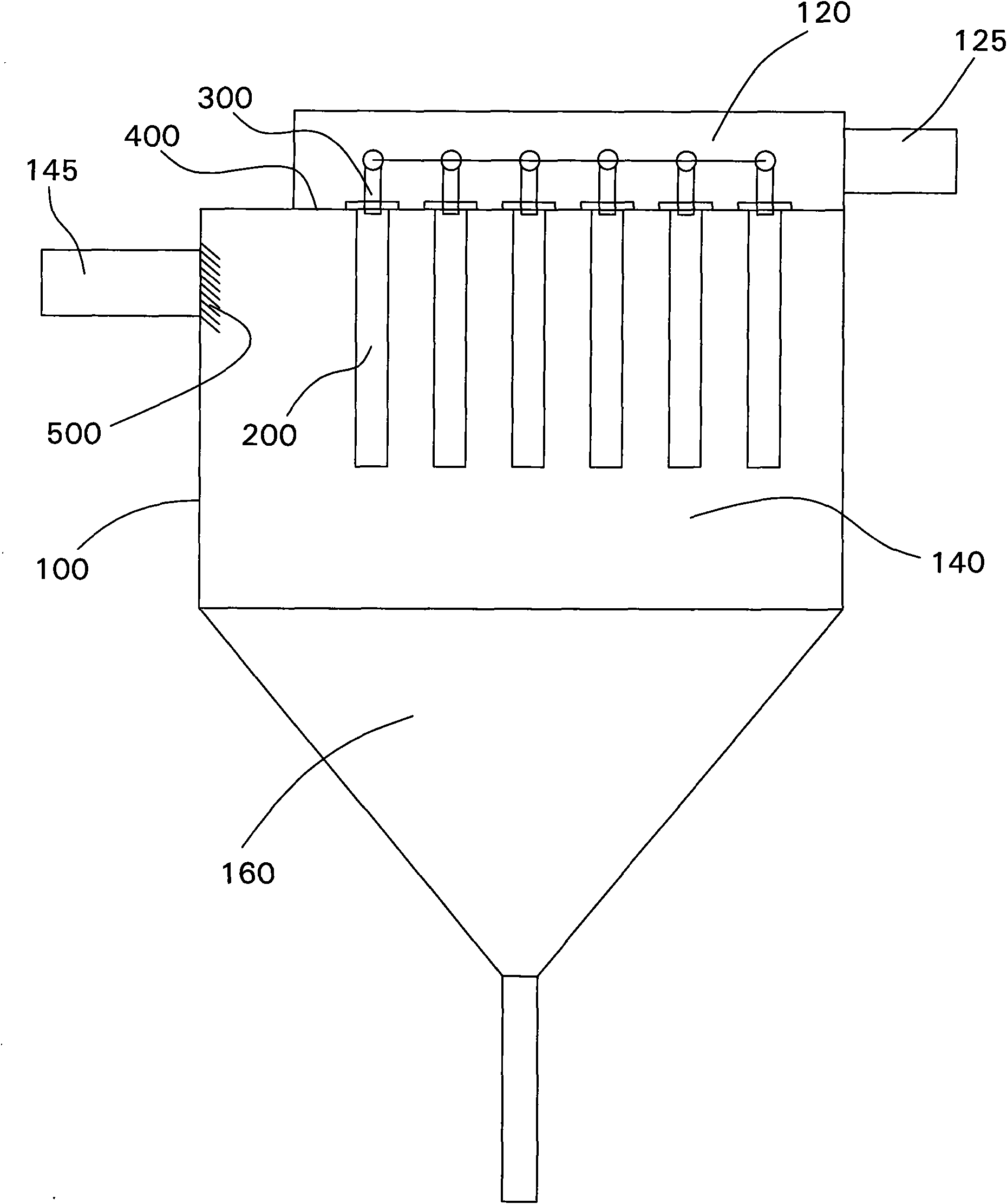
[0029]In this embodiment, the gas-solid separation device with a backflushing system of the present invention is applied to a biomass rapid pyrolysis liquefaction system. Among them, the biomass rapid pyrolysis liquefaction system generally includes a high-temperature cyclone primary separator and a high-temperature gas-solid separator for separating the remaining solid particles. The gas-solid separation device of the present invention can be used as a high-temperature gas-solid separator of the system.

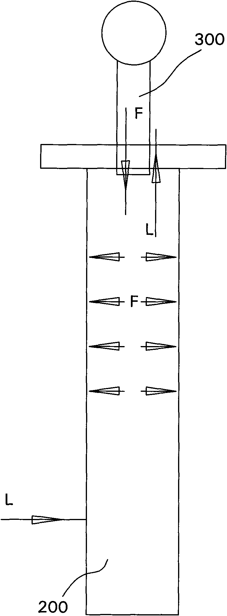
[0030] Please refer to figure 1 and figure 2 The gas-solid separation device of the present invention includes a device body 100 with a processing space inside, a crude gas inlet 145 disposed on one side of the device body 100, a gas outlet 125 disposed on the other side of the device body 100, and a gas outlet 125 disposed in the processing space. And the processing space is divided into the partition plate 400 of the filter chamber 140 and the clean gas chamber 120, the...

Embodiment 2

[0035] As another kind of scheme of the present invention, other parts are identical with embodiment 1, and difference is:

[0036] In this embodiment, the gas-solid separation device of the present invention is applied to an air dust removal and purification system. In addition, the gas-solid separation device is provided with three filter elements 200 at intervals, and the blowback system includes three blowback ports 300 correspondingly arranged on the top of each filter element 200 .

[0037] Among them, the back blowing system is provided with a timing controller for timing opening and closing of the back blowing system, so that the back blowing system is automatically opened after a certain time interval and automatically closed after a certain period of time.

[0038] In addition, the blowback system can control each blowback port 300 to work independently.


PUM


Abstract

The invention discloses a gas-solid separation device with a backblow system. The device comprises a device body provided with a treatment space inside, a crude gas inlet arranged on one side of the device body, a gas outlet arranged on the other side of the device body, a clapboard which is arranged in the treatment space and partitions the treatment space into a filtration chamber and an air-purifying chamber, at least one filter element which extends into the filtration chamber from the partition and is in gas communication with the filtration chamber and the air-purifying chamber, and the backblow system which is arranged in the air-purifying chamber and comprises at least one backblow port, wherein the crude gas inlet is communicated with the filtration chamber, the gas outlet is communicated with the air-purifying chamber, and the at least one backblow port is correspondingly arranged on the top of the filter element. The device adopts the backblow system to effectively blow off solid particles adhered to the filter element to avoid the phenomenon that the solid particles block the filter element, thereby ensuring the steady operation of the device.

Description

technical field [0001] The invention relates to a filter device, in particular to a gas-solid separation device used in a biomass energy conversion system. Background technique [0002] With the continuous development of the world economy, energy and environmental issues have become increasingly prominent. The main energy sources currently used by human beings are oil, natural gas and coal. According to the statistics of the International Energy Agency, the lifespan of these three kinds of energy for human exploitation on the earth is only 40 years, 50 years and 240 years respectively. The development of new energy has become a major issue related to the sustainable development of human society. [0003] Biomass energy is the solar energy stored in plants by the photosynthesis of plants and solar energy. It is estimated that the annual energy stored in plants is equivalent to 10 times the world's main fuel consumption, while the utilization of energy as energy is less tha...

Claims


Application Information

Patent Timeline
IPC IPC(8): B01D46/00B01D46/42
Inventor 陈平常厚春李祖芹马革杨红斌于建霞
Owner GUANGZHOU DEVOTION THERMAL TECH
Why Eureka
Try Eureka