Welding joint conveying device on inner surface of piping

A conveying device and inner surface technology, applied in auxiliary devices, welding equipment, welding equipment, etc., can solve the problems of limited working time, poor welding, unusable, etc., achieve correct welding, reduce costs, and expand the use of the effect

Active Publication Date: 2009-09-23
KOREA HYDRO & NUCLEAR POWER CO LTD
View PDF0 Cites 15 Cited by
  • Summary
  • Abstract
  • Description
  • Claims
  • Application Information

AI Technical Summary

Problems solved by technology

[0003] When carrying out the replacement construction of the above-mentioned steam generator, since the welding is carried out after the operation of the above-mentioned steam generator, the working time is limited in the above-mentioned working environment where the surrounding is radioactively contaminated, and in this kind of work People who work in the environment must wear bulky and heavy protective gear, so the movement, sight and work ability are greatly restricted. Therefore, a welding conveyor for performing operations such as the above is actually being developed recently.
[0004] The conventional track-type welding head conveying device is a way to move the above-mentioned welding head along the track, so when the above-mentioned welding head or the above-mentioned track is chang...

Method used


Image

  • Welding joint conveying device on inner surface of piping
  • Welding joint conveying device on inner surface of piping
  • Welding joint conveying device on inner surface of piping

Examples


Embodiment Construction

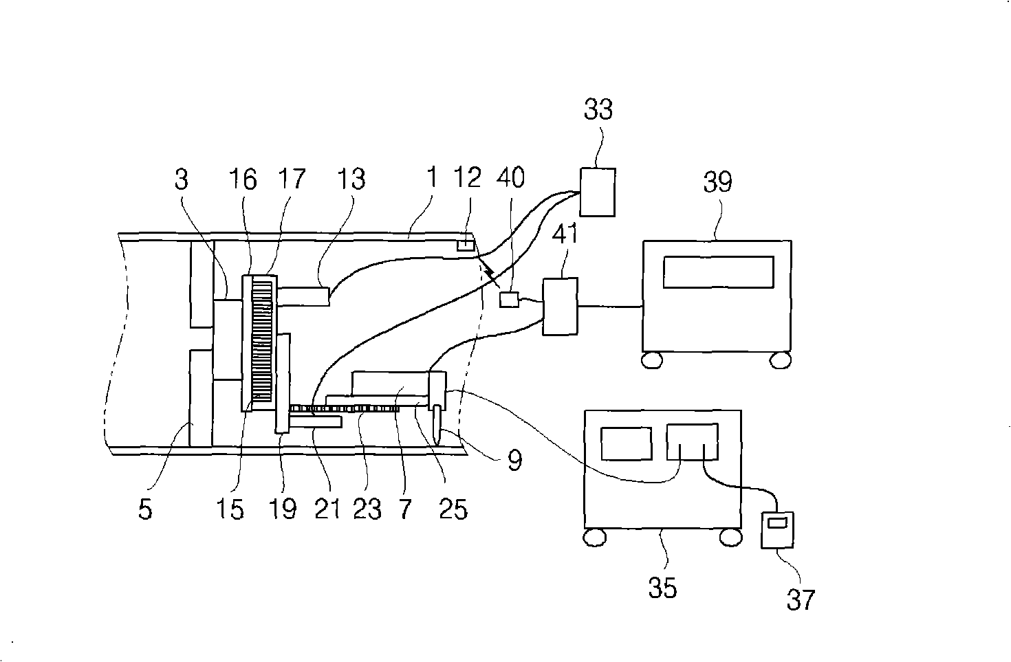
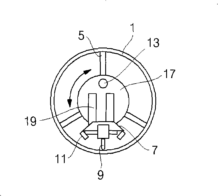
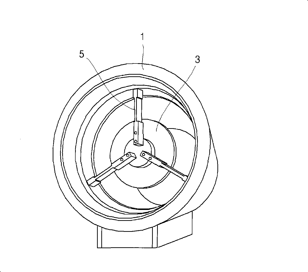
[0029] Hereinafter, an embodiment of the present invention will be described in detail with reference to the drawings.

[0030] refer to Figure 1 to Figure 6 According to an embodiment of the present invention, the structure of the welding head conveying device on the inner surface of the pipe includes: an interlocking chuck 3 used as a main body; The fixed part 5; the rotary drive motor 13 that generates the power required for welding the pipe 1 in the circumferential direction; the rotary drive part 15 that transmits the power of the rotary drive motor 13 to the rotary cover 17; protects the rotary drive part 15 and uses The conveying device in the longitudinal direction is installed in a manner that is formed, and the rotating cover 17 that rotates along the circumferential direction of the pipe 1 is transmitted from the above-mentioned rotating drive part 15; the rotating part mounting rod 19 connected to the above-mentioned rotating cover 17; The front and rear conveyin...


PUM


Abstract

The invention provides a welding joint conveying device on the inner surface of a piping. The length of a fixing part can be adjusted according to the size of the piping, and the device does not need to be remanufactured according to the size of the piping, so the cost can be lowered; and the device is not related with a manufacturing factory of welding joints, so the installation becomes easy, and the using range can be greatly enlarged. The device comprises a linkage chuck used as a main body, a fixing part for fixing the main body inside the piping, a rotary drive motor for generating power required by welding the piping along the circumferential direction, a rotary drive part for transferring the power of the rotary drive motor to a rotary cover, the rotary cover rotating along the circumferential direction of the piping, a rotary part mounting rod connected with the rotary cover, a back-and-forth conveying motor for generating power required by welding the piping along the lengthdirection, a drive part for transferring the power of the back-and-forth conveying motor to the length direction of a welding joint part, the welding joint part moving along the length direction of the piping, a motor controller, a wireless camera, a wireless receiving part, a camera controller, and a display part.

Description

technical field [0001] The present invention relates to a welding head conveying device for the inner surface of a pipe, and relates to a pipe interior capable of performing internal welding of the main pipe, that is, the connection part of the cooling material pipe of the atomic furnace, during the replacement construction of the steam generator in a nuclear power plant. Surface welding head conveyor. Background technique [0002] In general, the steam generator of a nuclear power plant is one of the most important core machines for generating steam required for electric power production by a steam turbine and a generator, and it is a device that functions as follows: The high-temperature, high-pressure primary cooling water (PRIMARY COOLANT) generated by the atomic furnace flows through the inner surface of the tube, heats the cold feed water (FEED WATER) outside the tube to generate steam, and then supplies the steam to the turbine. [0003] When carrying out the replac...

Claims


Application Information

Patent Timeline
IPC IPC(8): B23K37/00B23K5/22
Inventor 杨埈锡金太龙刘承英崔锡淳
Owner KOREA HYDRO & NUCLEAR POWER CO LTD
Why Eureka
Try Eureka