Method for preparing a microgap sleeve optical fiber prefabrication bar and method for drawing and preparing an optical fiber by microgap sleeve optical fiber prefabrication bar

An optical fiber preform and micro-gap technology, which is used in glass manufacturing equipment, glass fiber drawing devices, manufacturing tools, etc. The geometric parameters are stable, the shrinkage effect is good, and the strength is improved.

Active Publication Date: 2009-09-23
ZHONGTIAN TECH ADVANCED MATERIALS CO LTD +2
View PDF0 Cites 21 Cited by
  • Summary
  • Abstract
  • Description
  • Claims
  • Application Information

AI Technical Summary

Problems solved by technology

[0004] The purpose of the present invention is to provide a method for preparing a micro-gap sleeved optical fiber preform and a method for drawing an optical fiber, which solves the problem of unstable mode field diameter of the optical fiber preform produced by the existing sleeve method, and cladding geometric dimensions. Large fluctuations, and a series of problems such as breakpoints caused by micro-cracks in the sleeve and core rod. Under the premise of ensuring the performance of the optical fiber preform, the stretchable length of a single rod has been increased to more than 2000km

Method used


Image

  • Method for preparing a microgap sleeve optical fiber prefabrication bar and method for drawing and preparing an optical fiber by microgap sleeve optical fiber prefabrication bar
  • Method for preparing a microgap sleeve optical fiber prefabrication bar and method for drawing and preparing an optical fiber by microgap sleeve optical fiber prefabrication bar
  • Method for preparing a microgap sleeve optical fiber prefabrication bar and method for drawing and preparing an optical fiber by microgap sleeve optical fiber prefabrication bar

Examples


Embodiment Construction

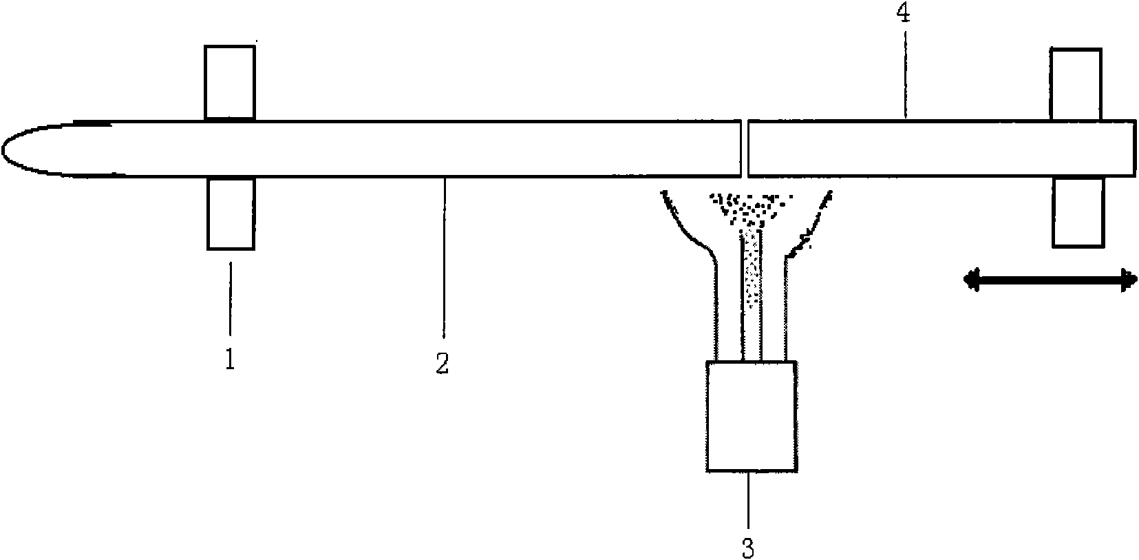
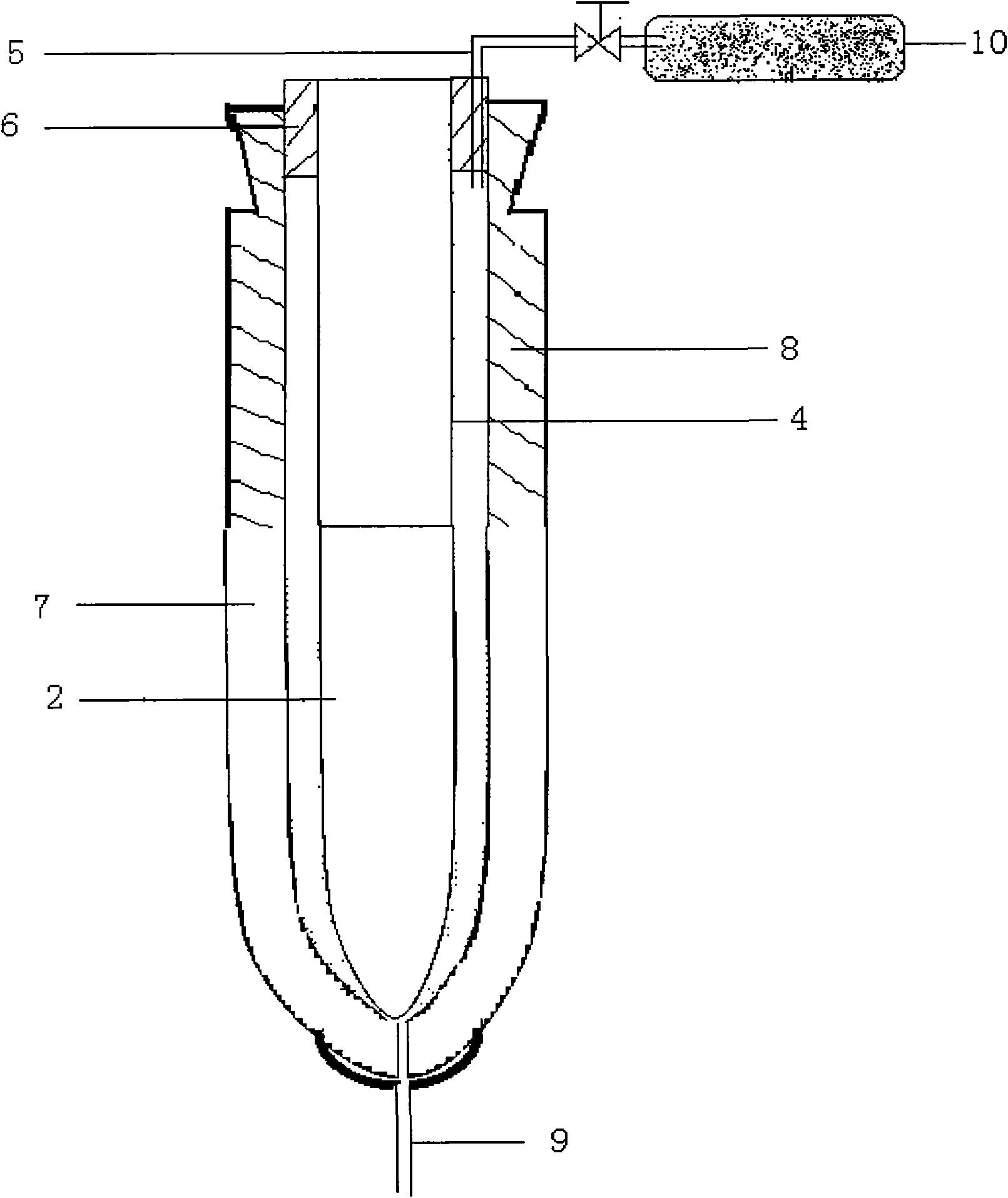
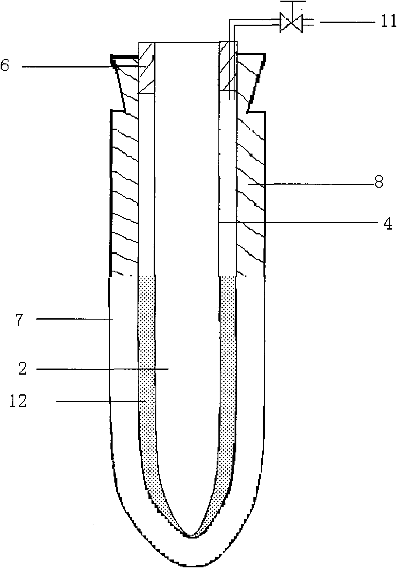
[0040] Refer to attached Figure 1~3 , preparation method of micro-gap sleeve optical fiber preform and method for drawing optical fiber thereof

[0041] The preparation method of the micro-gap sleeve optical fiber preform is as follows:

[0042] 1) handle

[0043] Using a glass lathe and using the hydrogen-oxygen flame of the blowtorch 3, the end faces of the mandrel 2 and the handle 4, the casing 7 and the tail handle 8 are melted at a high temperature of 1600 ° C to 1900 ° C, respectively, and then butt jointed, which is the joint handle. This process is performed in BC700- 250 double-chuck 1 glass lathe, the overall bow of the whole mandrel 2 and handle 4, sleeve 7 and tail handle 8 are controlled within 0-0.1mm / m after the handle is connected.

[0044] 2) Wash and dry

[0045] After the connection is completed, the surface of the mandrel 2 and the casing 7 needs to be cleaned for 2 hours with hydrofluoric acid with a concentration of 2% to 3% to remove surface pollutan...


PUM

PropertyMeasurementUnit
lengthaaaaaaaaaa
diameteraaaaaaaaaa
diameteraaaaaaaaaa

Abstract

The invention discloses a method for preparing a microgap sleeve optical fiber prefabrication bar and a method for drawing and preparing an optical fiber by the microgap sleeve optical fiber prefabrication bar and relates to the production of an optical fiber prefabrication bar and a method for drawing the wire by the optical fiber prefabrication bar. The method for preparing the microgap sleeve optical fiber prefabrication bar comprises the following steps: 1) a joint handle adopts a glass lathe and uses oxyhydrogen flame for separately abutting a core bar, a handle bar, a sleeve and a tail handle end face after high-temperature melting; 2) the joint handle is cleaned and dried, and 2-3 percent of hydrofluoric acid is used for cleaning the surfaces of the core bar and the sleeve for 2 hours so as to remove pollutants on the surfaces; and 3) in the assembly process, the cleaned and dried core bar is assembled into the sleeve, and then quartz sand is filled between the sleeve and the core bar so as to obtain the microgap prefabrication bar. The microgap sleeve optical fiber prefabrication bar is fixed on a collet of an optical fiber wire drawing tower and then molten so that an optical fiber can be drawn out from a lower opening of a wire-drawing stove and then is sequentially measured in diameter by a diameter measurer, cooled by a cooling pipe, coated, solidified by optical fiber coating and drawn by a main drawing device so as to reach a double-wire-collecting machine for optical fiber winding.

Description

technical field [0001] The preparation method of micro-gap sleeve optical fiber preform and the method for drawing optical fiber thereof of the present invention relate to a kind of optical fiber preform manufacture and optical fiber preform rod drawing method, specifically a kind of gap between the core rod and the sleeve Filling high-purity quartz sand to form a micro-gap casing optical fiber preform preparation method and the micro-gap preform drawing method, the preform prepared by this method has a low water peak, good geometrical size controllability, and a single rod can be drawn Large length can greatly improve equipment utilization and reduce costs. Background technique [0002] Under the guidance of the mainstream of "optical advance and copper retreat", optical fiber communication technology has continued to develop rapidly in recent years. It is estimated that the annual demand for domestic optical fiber will exceed 50 million core kilometers in 2010. However, th...

Claims


Application Information

Patent Timeline
Patent Type & Authority Applications(China)
IPC IPC(8): C03B37/012C03B37/027
CPCC03B37/02754C03B37/01205C03B2205/13C03B37/01297Y02P40/57
Inventor 薛济萍沈一春朱兆章薛驰庄卫星薛群山钱宜刚
Owner ZHONGTIAN TECH ADVANCED MATERIALS CO LTD
Why Eureka
Try Eureka