
Four-roller compact spinning device

A technology of compact spinning and rollers, which is applied to spinning machines, textiles, papermaking, and drafting equipment. cumbersome effect

Inactive Publication Date: 2009-09-23
张忠宝
View PDF0 Cites 3 Cited by
  • Summary
  • Abstract
  • Description
  • Claims
  • Application Information

AI Technical Summary

Problems solved by technology

The disadvantage of this three-gear transmission method is: (1) when spinning yarns of different materials, different draft ratios need to be set, that is, the ratio of the linear speed of the front roller to the linear speed of the output roller Keep it within an appropriate range, that is, to adjust the transmission of the front roller gear, the bridge gear and the output roller gear; while the traditional three-gear structure of the four-roller compact spinning device, because the front roller gear is directly in the front It is processed on the roller, and the output roller gear is directly processed on the output roller. Its diameter, number of teeth and position are already fixed, which makes it difficult to adjust the draft ratio by changing the structure of the bridge gear alone. Adjustment is even impossible to adjust; and if both or all of the front roller gear, the bridge gear and the output roller gear are changed at the same time, the front roller or the output roller needs to be replaced, which has the disadvantages of high cost and cumbersome operation; (2) The front roller gear, the bridge gear and the output roller gear are arranged around the collecting pipe, and the space enclosed by the three gears is limited, so that the radial cross-sectional area of ​​the collecting pipe used is limited, that is, the negative pressure suction in the collecting pipe is limited. The radial cross-sectional area of ​​the channel, and the size of the radial cross-sectional area of ​​the negative pressure suction channel can affect the distribution uniformity of the negative pressure in the suction channel, and finally affect the balance of the negative pressure at each accumulation hole of the accumulation pipe; when When the accumulation tube is long and there are many accumulation holes, the negative pressure distribution at each accumulation hole may be uneven, and the difference is large, which will eventually affect the effect of the accumulation spinning

Method used


Image

  • Four-roller compact spinning device
  • Four-roller compact spinning device
  • Four-roller compact spinning device

Examples


Embodiment 1

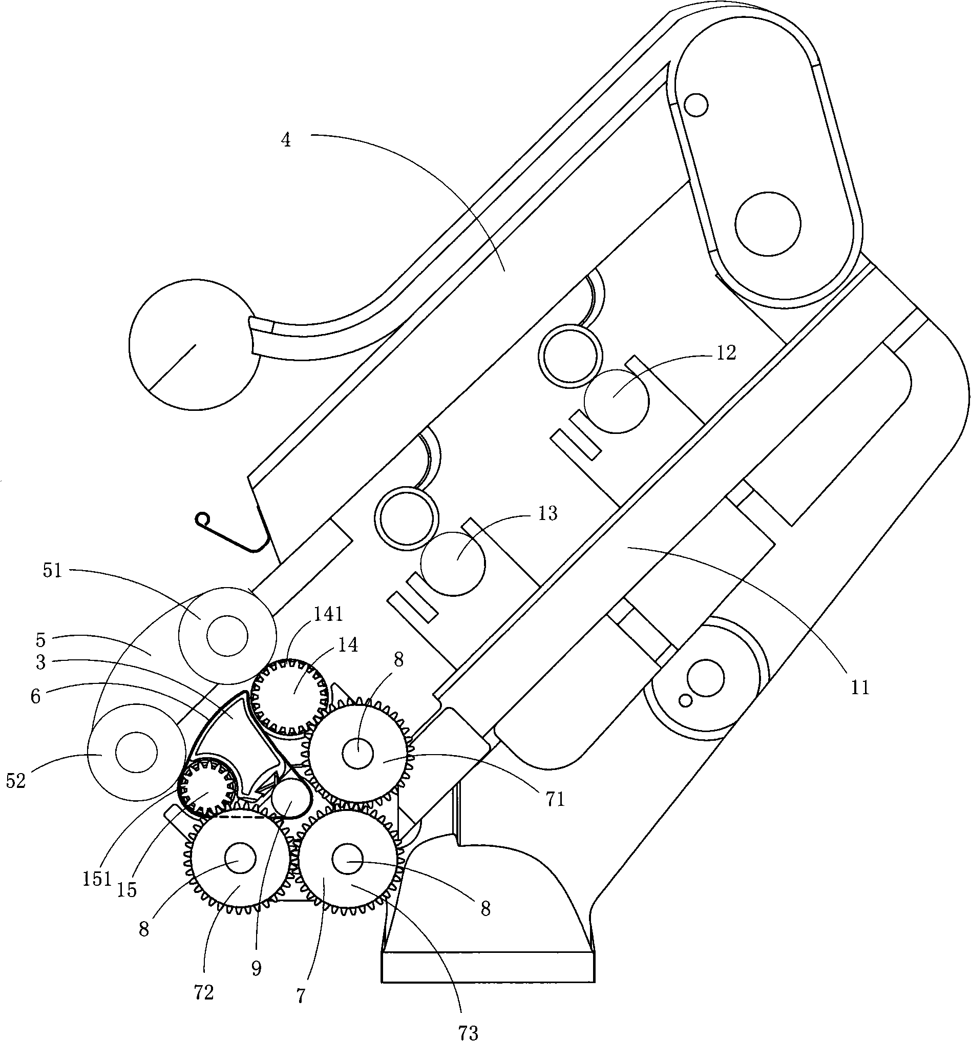
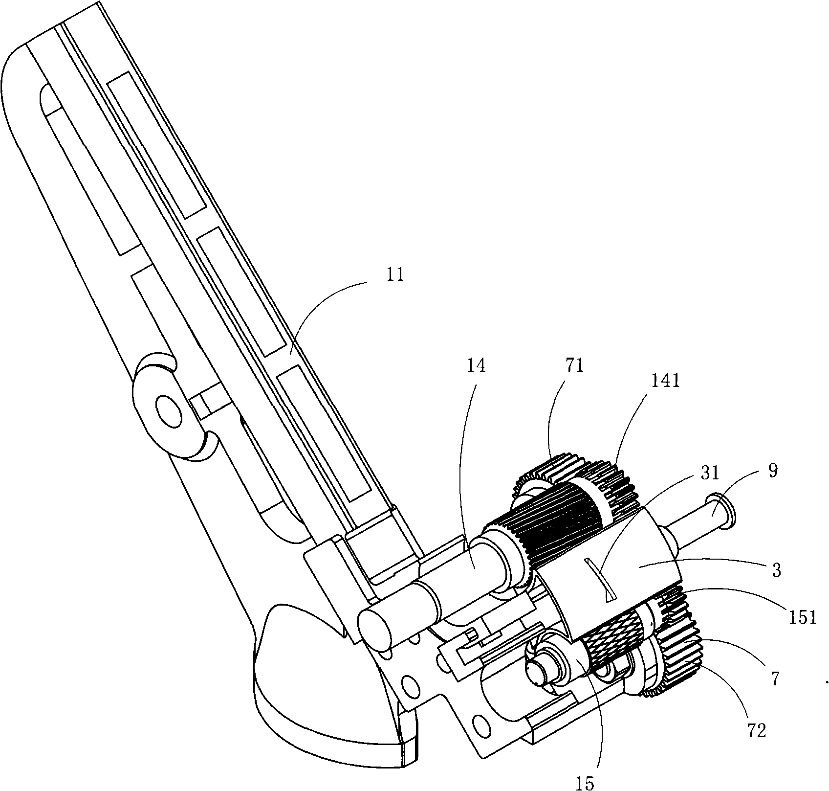
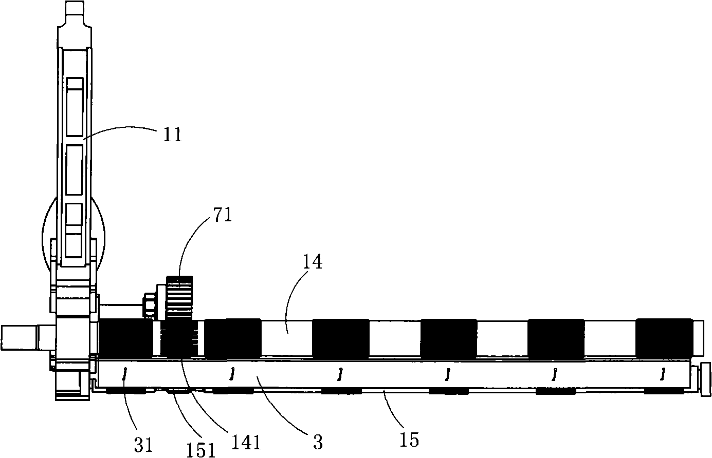
[0026] Figure 1 to Figure 3 A first embodiment of the invention is shown, in which figure 1 It is a structural schematic diagram of the present invention; figure 2 yes figure 1 A schematic diagram of a partial three-dimensional structure of the four-roller compact spinning device shown; image 3 yes figure 1A schematic diagram of the structure of the four-roller compact spinning device shown with some components removed.

[0027] This embodiment is a four-roller compact spinning device, see Figure 1 to Figure 3 , including roller seat 11, rear roller 12, middle roller 13, front roller 14, output roller 15, gathering pipe 3, cradle 4, saddle frame 5, front roller top roller 51, output top roller 52, grid ring 6 and A bridge gear assembly 7 arranged below the collecting pipe 3; the rear roller 12, the middle roller 13, the front roller 14, the collecting pipe 3 and the output roller 15 are sequentially arranged on the roller seat 11 along the advancing direction of the y...

Embodiment 2

[0034] Figure 4 It is a structural schematic diagram of the second structure of the present invention, showing the second specific implementation mode of the present invention.

[0035] This embodiment is basically the same as Embodiment 1, except that the bridge gear assembly 7 is arranged below the end pipe section at one side of the collecting pipe 3 . Described front roller gear 141 is a gear that is assembled on the front roller 14, and described front roller 14 is split piece; Described output roller gear 151 is a gear that is assembled on the output roller 15, and described output roller 15 is split parts.

[0036] The advantage of this embodiment is that the output roller gear 151 and the front roller gear 141 are replaceable gears, and the maintenance operation cost is low.

Embodiment 1 and Embodiment 2

[0037] Embodiment 1 and embodiment 2 have the following advantages:

[0038] (1) In Embodiment 1 and Embodiment 2, when spinning yarns of different materials, different draft ratios need to be set, so that the ratio of the linear speed of the front roller to the linear speed of the output roller remains at one Within the appropriate range, that is to say, it is necessary to adjust the transmission of the front roller gear, the bridge gear and the output roller gear; and the traditional three-gear structure of the four-roller compact spinning device, because the front roller gear is directly processed on the front roller The output roller gear is directly processed on the output roller, and its diameter, number of teeth and position are already fixed, so that the adjustment of the draft ratio by changing the structure of the bridge gear alone is greatly restricted and difficult to adjust Even can not be adjusted; and if change both or all of the front roller gear, the bridge ge...


PUM


Abstract

The invention discloses a four-roller compact spinning device, which comprises an intermediate gear assembly arranged below a gathering tube. The intermediate gear assembly comprises a master intermediate gear and a first auxiliary intermediate gear and a second auxiliary intermediate gear which are respectively arranged at two sides of the master intermediate gear. A front roller is provided with a front roller gear and output rollers are respectively provided with output roller gears. The front roller drives the first auxiliary intermediate gear to rotate by the front roller gear. The first auxiliary intermediate gear drives the master intermediate gear to rotate. The master intermediate gear drives the second auxiliary intermediate gear to rotate. The second auxiliary intermediate gear drives the output rollers to rotate by the output roller gears. The output roller drives a lattice apron to rotate and simultaneously drives an output leather roller to rotate. The spinning device has the advantages of being convenient for adjusting the draw ratio of the front roller to the output rollers, simultaneously increasing the radial sectional area of the gathering tube as much as possible and increasing the negative pressure distribution balance at all gathering holes, thus improving spinning effect.

Description

technical field [0001] The invention belongs to the technical field of spinning machine structure design, and in particular relates to a four-roller compact spinning device. Background technique [0002] The traditional three-roller compact spinning is to add a hairiness converging device consisting of a gathering tube, a grid ring, a front roller top roller, and an output top roller on the basis of the traditional spinning process. The front roller top roller and the output top roller Set on the saddle frame, the saddle frame is equipped with a transmission gear, so that the front roller top roller and the output top roller rotate at the same speed through gear transmission; the saddle frame is fixed on the cradle, after the cradle is put down, the front roller top roller and the output top roller The top rollers press the yarn against the front rollers and the collecting tube. The rotation of the front roller drives the grid ring to rotate around the surface of the collec...

Claims


Application Information

Patent Timeline
Patent Type & Authority Applications(China)
IPC IPC(8): D01H5/22D01H5/32D01H5/70
Inventor 张忠宝
Owner 张忠宝
Learn More